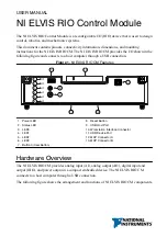


The following figure shows the AI topology of the NI ELVIS RIO CM.
Figure 3. NI ELVIS RIO CM AI Circuitry
MUX
ADC
AI0
AI1
AI2
AI3
AI0
AI1
AI2
AI3
0–5 V
MXP A
MXP B
AO Channels
The NI ELVIS RIO CM MXP connectors A and B have two AO channels per connector, AO0
and AO1, which you can use to generate signals of 0 V to 5 V. Each channel has a dedicated
digital-to-analog converter (DAC), which allows all AO channels to update simultaneously.
The DACs for the AO channels are controlled by a serial communication bus from the FPGA.
MXP connectors A and B share this bus and therefore, all channels must share the same
update rate.
The following figure shows the AO topology of the NI ELVIS RIO CM.
Figure 4. NI ELVIS RIO CM AO Circuitry
DAC
DAC
0–5 V
AO0
AO1
MXP A
MXP B
DAC
DAC
AO0
AO1
Converting Raw Data Values to Voltage
You can use the following equations to convert raw AI and AO data values to volts:
V = Raw Data Value × LSB Weight
LSB Weight = Nominal Range ÷ 2
Resolution
where
Raw Data Value is the value returned by the FPGA I/O node,
LSB Weight is the value in volts of the increment between data values,
4
|
ni.com
|
NI ELVIS RIO CM User Manual


