


NI PXIe-5624R Calibration Procedure
|
© National Instruments
|
7
4.
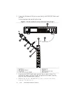
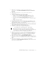
Connect the power sensor to splitter output 2 using the SMA (f)-to-N (f) adapter.
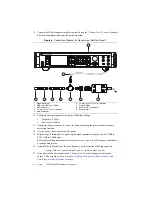
The following figure illustrates the hardware setup.
Figure 1.
Connection Diagram for Measuring at Splitter Output 2
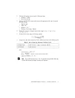
5.
Configure the signal generator using the following settings:
•
Frequency: 5 MHz
•
Power level: 4 dBm
6.
Configure the power sensor to correct for frequency using the power sensor frequency
correction function.
7.
Use the power sensor to measure the power at the frequency from step 6.
8.
Repeat steps 5 through 7, by updating the signal generator frequency from 5 MHz to
2.005 GHz in 5 MHz steps.
Record the resulting measurements as
splitter output 2 power
. Each frequency should have
a corresponding value.
9.
Disconnect the power sensor and 50
Ω
terminator from the power splitter.
10. Connect the power sensor to splitter output 1 using an SMA (m)-to-N (f) adapter.
1
Signal Generator
2
SMA (m)-to-SMA (m) Cable
3
Power Sensor
4
SMA (f)-to-N (m) Adapter
5
6 dB Attenuator
6
3.5 mm (m) to 3.5 mm (m) Adapter
7
Power Splitter
8
50
Ω
Terminator
1
2
8
7
6
5
4
3


