NI PXIe-5624R Calibration Procedure
|
© National Instruments
|
19
7.
Call
niIFDig ExternalCal v1 Host.lvclass:Amplitude Cal
Initialize.vi
. Wire
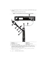
External 10 MHz Reference Clock
to the
reference clock
source
input.
8.
Call
niIFDig ExternalCal v1 Host.lvclass:Amplitude Cal
Configure.vi
.
9.
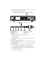
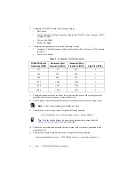
Configure the signal generator using the following settings:
•
Frequency: value of the
frequency to generate (Hz)
output from
niIFDig
External Cal v1 Host.lvclass:Amplitude Cal Configure.vi
•
Power level: value of the
power to generate (dBm)
output from
niIFDig
External Cal v1 Host.lvclass:Amplitude Cal Configure.vi
plus
12 dB
•
Reference Clock source: Internal
10. Configure the power sensor to correct for the
frequency to generate (Hz)
output from
niIFDig External Cal v1 Host.lvclass:Amplitude Cal Configure.vi
using the power sensor frequency correction function.
11. Measure the power of the signal present at splitter output 1 of the power splitter using the
power sensor. Record this value as the
measured input power
.
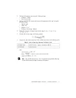
12. Calculate the
corrected input power
using the following equation:
corrected input power
=
measured input power + splitter balance
Tip
Find the
splitter balance
by choosing the correct data point from the
Characterizing Power Splitter Balance
section. Remember that certain frequencies
are not measured due to harmonics aliasing back on the fundamental.
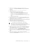
13. Call
niIFDig ExternalCal v1 Host.lvclass Amplitude Cal Adjust.vi
.
Wire the
corrected input power
calculated in step 12 to the
actual power (dBm)
input.
Wire the
frequency
output from
niIFDig External Cal v1 Host.lvclass:
Amplitude Cal Configure.vi
to the
actual frequency (Hz)
input.
14. Repeat steps 8 through 13 until the
amplitude calibration complete
output of
niIFDig
ExternalCal v1 Host.lvclass:Amplitude Cal Adjust.vi
returns a value of
TRUE.
15. Call
niIFDig ExternalCal v1 Host.lvclass:Close External
Calibration.vi
. Set the
write calibration to hardware?
input to TRUE to store the
results to the NI 5624R flash memory.


