


NI PXIe-5624R Calibration Procedure
|
© National Instruments
|
5
Test Conditions
The following setup and environmental conditions are required to ensure the NI 5624R meets
published specifications:
•
Keep cabling as short as possible. Long cables act as antennas, picking up extra noise that
can affect measurements.
•
Verify that all connections, including front panel connections and screws, are secure.
•
Maintain an ambient temperature of 23 °C ±5 °C.
•
Keep relative humidity between 10% and 90%, noncondensing.
•
Allow a warm-up time of at least 20 minutes after the chassis is powered on, the
NI LabVIEW Instrument Design Libraries for IF Digitizers software is loaded by the host,
and the host recognizes the NI 5624R. The warm-up time ensures that the NI 5624R and
test instrumentation are at a stable operating temperature.
•
Perform self-calibration on the NI 5624R.
•
Plug the PXI Express chassis and the test equipment into the same power strip to avoid
ground loops.
•
Use a torque wrench appropriate for the type of RF connector that you are using.
•
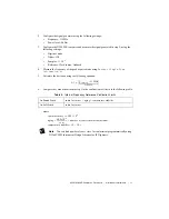
In each verification procedure, insert a delay between configuring all devices and acquiring
the measurement. Adjust this delay depending on the instruments used but make sure it is
at least 5,000 ms for the first iteration and 10 ms for each other iteration.
•
Ensure that the PXI Express chassis fan speed is set to HIGH, that the fan filters, if present,
are clean, and that the empty slots contain filler panels. For more information about cooling,
refer to the
Maintain Forced-Air Cooling Note to Users
document available at
ni.com/
manuals
.
Initial Setup
Refer to the
NI PXIe-5624R Getting Started Guide
for information about how to install the
software and hardware and how to configure the device in Measurement & Automation Explorer
(MAX).
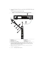
Connect the SMA (f)-to-N (m) adapter to the RF OUT port of the signal generator.
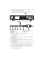
Characterizing the Test System
You use the measured response of the test system during verification tests.
The power splitter and attenuation response is measured at the RF input frequencies used in the
verification and adjustment tests.
Caution
The connectors on the device under test (DUT) and test equipment are
fragile. Perform the steps in these procedures with great care to prevent damaging any
DUTs or test equipment.


