3
Parts List, continued
10.
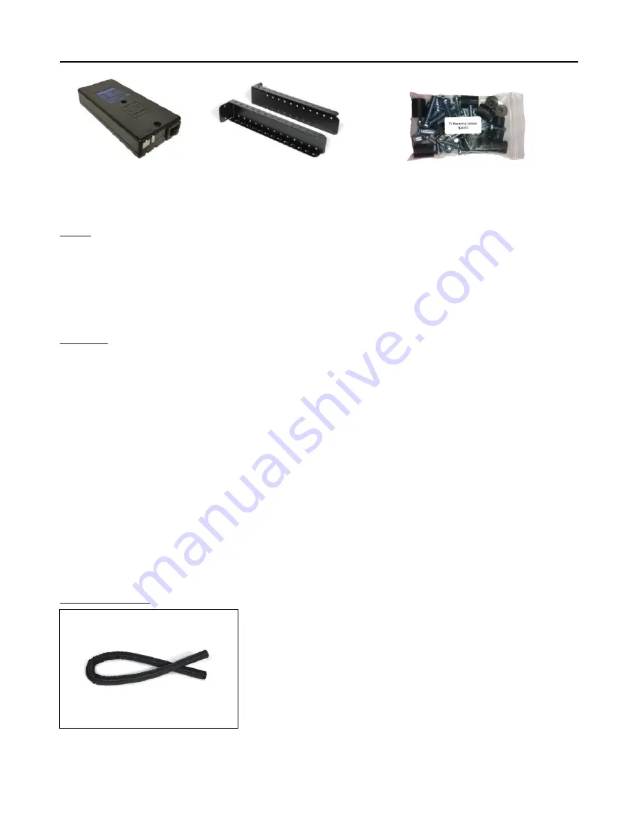
Control Box
11.
Top Support Brackets (2)
12.
Assorted TV Mounting Screws
(10 ½” x 3 ¾” x 1 ½”)
(14” x 2 ¾”) (6 ½” x 4”)
Cables
Motor Cable
– Black cable with white, six-pin plugs. Use this cable to connect the Lift Column to the Control Box
(using slot #1 on the Control Box). Three feet long.
Power Cable
– Connects Control Box to power outlet. Three feet long.
RF Cable (only present if you ordered the RF version of the Lift System)
– Use to connect the RF Receiver to the
Control Box. Ends have telephone-style connectors. One foot long.
Hardware
13
.
Two (2) -- Screen Locks
(In bag labeled PDM-0108 - Located in box with Part #5 and #6)
14.
Eight (8) -- 6mm x 16mm Flat Head Machine Screw
15.
Sixteen (16) -- 6mm x 12mm Button Head Machine Screw
16.
Two (2) -- 1½” x ¼” Steel Threaded Taper Pins (For Floating Top)
17.
Four (4) -- 3/8 - 16 x ¾” Button Head Machine Screw
19.
Two (2) -- #10 x 1 ¾” Flat Head Wood Screw
20.
Eighteen (18) -- #10 x ¾” Truss Head Wood Screw
21.
Four (4) -- #8 x ¾” Flat Head Wood Screw (For IR controls only)
22.
RF Controls or IR Controls (see explanation on page 6)
23.
Two (2) -- Allen Wrenches – 4mm and 7/32”
24.
One (1) -- “Snakeskin” Wire Management Sleeve – 4 feet long
25.
Three (4) -- Velcro end Ties, for use with Wire Management Snakeskin
26.
Three (4) -- Plastic Ties, also for use with Wire Management Snakeskin
27.
Four (4) -- Square Multi Mount Washers
28.
Four (4) -- Wire Clips
29.
Four (4) – Lid Catch Brackets w/ (8) #10 x ¾” THWS
Wire Management
The Lift System has no exposed gears or moving parts that can
damage your wires, so wire management is simple. We have
included a four-foot long “SNAKESKIN” sleeve, which is a state-of-
the-art wire bundling and protection system (the sleeve can be cut
shorter if you wish). The System also includes 4 Velcro end ties and 4
plastic ties. Use the Velcro ties at the ends of the SNAKESKIN, to
close the ends of the sleeve and to keep the wires together inside it.
Use the plastic ties to fasten the cable bundle in a fixed position, so it
moves up and down with the lift.
Summary of Contents for L-45
Page 1: ...TV Lift System Model L 45 Installation Instructions ...
Page 20: ...20 ...
Page 22: ...22 Supplemental Page C Connect the Lift to Home Control System ...
Page 23: ...23 ...
Page 24: ...24 866 500 5438 ...


