


5
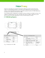
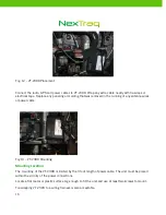
External mounting tabs are provided that allow the VT-2300 to be secured to the chassis of the
vehicle. If you are replacing a Wahoo 2 or VT-2200, the VT-2300 will fit in the area you have the
previous unit secured. Additional equipment is required to properly mount the VT-2300 hardware and
is provided in the installation kit for each VT-2300.
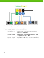
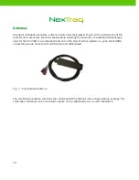
The VT-2300 connector configuration is composed of unique connectors to eliminate the chance of an
installer incorrectly wiring the unit. Five connectors make up the VT-2300’s configuration: power,
GPIO, a serial port interface, GSM antenna connector and GPS antenna connector.
VT-2300 Wiring Diagrams
Fig – 2 -Schematic of VT-2300
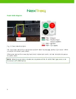
Pin Out Power Cable
Pin
Signal
Color
1
Ground
Black
2
Positive Input
Sensor 1 / GPIO1
Green
3
Ignition
White
4
12V Supply
Red
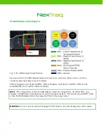
Pin Out IO – VT-2300 Adapter Cable
Pin
Signal
Color
1
One-Wire Data – Temperature
Sensor/ Driver ID
Green
2
Negative Input Sensor 1/GPIO2 Yellow
3
Negative Input Sensor 2/GPIO3 Blue
4
Sink Output / GPIO4
Orange/White
5
Positive Output Sensor 2 /
GPIO5
Blue/White
6
Ground
Black


