


14
NOTE: The first choice for power connections should always be at the ignition column. Use cable-
splicing interconnects (such as Scotch locks) or solder to secure connections.
If the column is unobtainable or if there are too many other devices wired to the column, the
input wires behind the fuse box can be a valid connection alternative.
If connections must be made to fuses at the fuse box, using a fuse tap is acceptable when all
other options are exhausted.
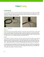
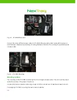
Ignition
An ignition source is also required for proper installation of VT-2300. Connect the white wire to the
vehicle ignition source. This wire can be found in close proximity to the main power wire. Be sure that
the tapped wire is a vehicle ignition wire and not an accessory wire. Some vehicles have wires that are
only powered when the vehicle is running; this is the preferred wire. Ignition wires maintain a voltage
through the crank. The best place to pull power is at the ignition harness leading to the ignition switch.
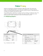
See Appendix A for specifications relating to power, ground, ignition and sensors.
IMPORTANT: Late Model Vehicle Installation
When installing a VT-2300 in any late model vehicle, verify all connections using a digital multimeter.
In some instances, obtaining power will require direct connection to the battery.
CAN-based vehicles will contain data lines that will show voltage on the line itself (usually 5V), but the
line is actually a data line. Most late model vehicles can utilize CAN-based ignition and accessory
circuits so the ignition line running down the center of the steering column is actually a data circuit.
Connecting VT-2300 to these circuits can and will cause the unit to malfunction and may damage the
OEM electronic modules within the vehicle.
As a rule of thumb, use the thickest wires as they carry the most amperage.
If there any questions, please contact Customer Support at 800.358.6178.