39
T H E S M A R T S O L U T I O N F O R E N E R G Y E F F I C I E N C Y
C o n s o l e s
R e v. : 3 0 J u n e , 2 0 0 8 B
w w w. c l i m a t e m a s t e r. c o m
Typical Wiring Diagram - TRC Units 50Hz
with DXM & MPC Controller
Page 1: ...Pump Applications 14 Ground Loop Heat Pump Applications 15 Ground Water Heat Pump Applications 16 Water Quality Standards 18 Electrical Wiring Line Voltage 19 21 Electrical Wiring Low Voltage 22 Therm...
Page 2: ......
Page 3: ...ed Water Valve A G N Autoflow 2 25 Gpm Ton B H P Autoflow 3 0 Gpm Ton C J Q Motorized Water Valve Afr 2 25 D K R Motorized Water Valve Afr 3 0 E L T Secondary Circulation Pump U V W Water Circuit Opti...
Page 4: ...mote Mounted w DXM MPC G 208 230 60 1 B 20Amp Plug Cord D Disconnect Switch 15Amp Fuse F Disconnect Switch Non Fused H 20Amp Plug Cord Receptacle Disconnect Switch 15Amp Fuse K 20Amp Plug Cord Recepta...
Page 5: ...in the compressor To avoid leakage of compressor oil refrigerant lines of the compressor must be sealed after it is removed CAUTION To avoid equipment damage DO NOT use these units as a source of hea...
Page 6: ...ed for installation above false ceiling or in a ceiling plenum Other unit configurations are typically installed in a mechanical room The installation site chosen should include adequate service clear...
Page 7: ...ttings in 1 2 1 2 1 2 1 2 1 2 Optional EPT Fittings in 1 2 1 2 1 2 1 2 1 2 Condensate Connection Size I D Vinyl Hose In mm 5 8 15 9 5 8 15 9 5 8 15 9 5 8 15 9 5 8 15 9 Air Coil Size Dimensions h x w i...
Page 8: ...imensions h x w in mm 8 x 26 20 3 x 66 0 10 x 26 25 4 x 66 0 10 x 32 25 4 x 81 2 Filter Size Bottom Return in cm 1 10 x 30 x 1 25 4 x 76 2 x 2 5 2 10 x 16 x 1 25 4 x 40 6 x 2 5 Front Return In cm 1 7...
Page 9: ...D Vinyl Hose In mm 5 8 15 9 Air Coil Size Dimensions h x w in mm 8 x 26 20 3 x 66 0 10 x 26 25 4 x 66 0 10 x 32 25 4 x 81 2 Filter Size Bottom Return in cm 1 10 x 30 x 1 25 4 x 76 2 x 2 5 10 x 36 x 1...
Page 10: ...rated hose assemblies are available for use with ClimateMaster Console Units Use the following guidelines when installing supply and return hose assemblies 1 Install supply and return hoses fitted wi...
Page 11: ...tly Horizontal runs of condensate hose should be pitched downward 1 4 inch minimum for every foot 10mm per 46cm of hose Avoid low points because dirt collects in these areas and may cause blockage If...
Page 12: ...Hose Optional Disconnect Box mounted to cabinet not chassis Optional Motorized Water Valve Optional Autoflow Valve Water Connections 5 8 15 9 mm OD Copper 1 2 IPT or 1 2 EPT 7 5 191 3 42 87 3 56 90 Ri...
Page 13: ...is not available tighten finger tight plus one quarter turn Tighten steel fittings as necessary Optional pressure rated hose assemblies designed specifically for use with ClimateMaster units are avai...
Page 14: ...valve for use in variable speed pumping systems may also be included in the hose kit The piping system should be flushed to remove dirt piping chips and other foreign material prior to operation see...
Page 15: ...water circuit insulation CAUTION CAUTION Ground Loop Heat Pump Applications Test individual horizontal loop circuits before backfilling Test vertical U bends and pond loop assemblies prior to install...
Page 16: ...rect use A monitoring plan should be implemented in these probable scaling situations Other water quality issues such as iron fouling corrosion prevention and erosion and clogging should be referenced...
Page 17: ...side of any field provided shut off valves and connected to the heat pump controls in series with the built in refrigerant circuit high pressure switch to disable compressor operation if water pressur...
Page 18: ...lloy bronze or brass cast components are OK to 0 5 ppm Ammonia ion All 0 5 ppm as hydroxide chloride nitrate and sulfate compounds Maximum Maximum Allowable at maximum water temperature Chloride Level...
Page 19: ...Code whichever is applicable Power Connection Line voltage connection is made by connecting the incoming line voltage wires to the L side of the contactor Consult Tables 4 through 5 for correct fuse...
Page 20: ...55 8 1 0 11 6 14 3 25 G 208 230 60 1 197 254 1 5 2 24 0 0 6 5 8 7 1 15 E 265 60 1 239 292 1 4 2 25 0 0 4 4 6 5 7 15 TRC15 G 208 230 60 1 197 254 1 6 1 30 0 0 8 6 9 8 4 15 E 265 60 1 239 292 1 4 7 28...
Page 21: ...B only required with systems employing remote mounted thermostats Figure 3 Typical Field Installed Wiring WARNING To avoid possible injury or death due to electrical shock open the power supply disco...
Page 22: ...TRC models include digital display unit mounted controls see picture below Either manual changeover MCO or auto changeover ACO controls are available as indicated by the model number The room temperat...
Page 23: ...he position of the back plate mounting holes and drill holes with a 3 16 5mm bit Install supplied anchors and secure plate to the wall Thermostat wire must be 18 AWG wire Wire the appropriate thermost...
Page 24: ...MATEMASTER WATER SOURCE HEAT PUMPS Co n sole s R ev 30 J u n e 2008B 24 ClimateMaster Water Source Heating and Cooling Systems Typical Wiring Diagram Manual Change Over CCE Units Rev A with CXM Contro...
Page 25: ...25 THE SMAR T SOLUTION FOR ENERGY EFF IC IE NC Y C ons oles Rev 3 0 June 2 0 0 8 B www climatemaster com Typical Wiring Diagram Auto Change Over CCE Units Rev A with CXM Controller...
Page 26: ...TER WATER SOURCE HEAT PUMPS Co n sole s R ev 30 J u n e 2008B 26 ClimateMaster Water Source Heating and Cooling Systems Typical Wiring Diagram Manual Auto Change Over CCE Units Rev B TRC Units with CX...
Page 27: ...27 THE SMAR T SOLUTION FOR ENERGY EFF IC IE NC Y C ons oles Rev 3 0 June 2 0 0 8 B www climatemaster com Typical Wiring Diagram Remote Mounted Thermosat CCE TRC Units with CXM Controller...
Page 28: ...CL I MATEMASTER WATER SOURCE HEAT PUMPS Co n sole s R ev 30 J u n e 2008B 28 ClimateMaster Water Source Heating and Cooling Systems Typical Wiring Diagram CCE TRC Units with CXM MPC Controller...
Page 29: ...29 THE SMAR T SOLUTION FOR ENERGY EFF IC IE NC Y C ons oles Rev 3 0 June 2 0 0 8 B www climatemaster com Typical Wiring Diagram Manual Change Over CCE Units Rev A with DXM Controller...
Page 30: ...MATEMASTER WATER SOURCE HEAT PUMPS Co n sole s R ev 30 J u n e 2008B 30 ClimateMaster Water Source Heating and Cooling Systems Typical Wiring Diagram Auto Change Over CCE Units Rev A with DXM Control...
Page 31: ...31 THE SMAR T SOLUTION FOR ENERGY EFF IC IE NC Y C ons oles Rev 3 0 June 2 0 0 8 B www climatemaster com Typical Wiring Diagram Manual Auto Change Over CCE Units Rev B TRC Units with DXM Controller...
Page 32: ...TEMASTER WATER SOURCE HEAT PUMPS Co n sole s R ev 30 J u n e 2008B 32 ClimateMaster Water Source Heating and Cooling Systems Typical Wiring Diagram Remote Mounted Thermostat CCE TRC Units with DXM Con...
Page 33: ...33 THE SMAR T SOLUTION FOR ENERGY EFF IC IE NC Y C ons oles Rev 3 0 June 2 0 0 8 B www climatemaster com Typical Wiring Diagram CCE TRC Units with DXM MPC Controller...
Page 34: ...TEMASTER WATER SOURCE HEAT PUMPS Co n sole s R ev 30 J u n e 2008B 34 ClimateMaster Water Source Heating and Cooling Systems Typical Wiring Diagram Manual Auto Change Over TRC Units 50Hz with CXM Cont...
Page 35: ...35 THE SMAR T SOLUTION FOR ENERGY EFF IC IE NC Y C ons oles Rev 3 0 June 2 0 0 8 B www climatemaster com Typical Wiring Diagram Remote Mounted Thermostat TRC Units 50Hz with CXM Controller...
Page 36: ...CL I MATEMASTER WATER SOURCE HEAT PUMPS Co n sole s R ev 30 J u n e 2008B 36 ClimateMaster Water Source Heating and Cooling Systems Typical Wiring Diagram TRC Units 50Hz with CXM DXM Controller...
Page 37: ...37 THE SMAR T SOLUTION FOR ENERGY EFF IC IE NC Y C ons oles Rev 3 0 June 2 0 0 8 B www climatemaster com Typical Wiring Diagram Manual Auto Change Over TRC Units 50Hz with DXM Controller...
Page 38: ...EMASTER WATER SOURCE HEAT PUMPS Co n sole s R ev 30 J u n e 2008B 38 ClimateMaster Water Source Heating and Cooling Systems Typical Wiring Diagram Remote Mounted Thermostat TRC Units 50Hz with DXM Con...
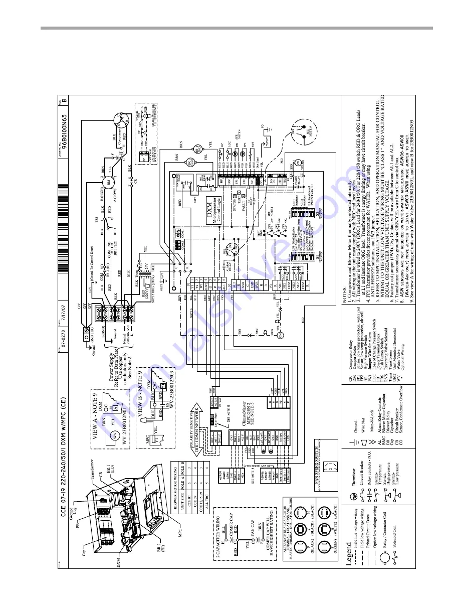
Page 39: ...39 THE SMAR T SOLUTION FOR ENERGY EFF IC IE NC Y C ons oles Rev 3 0 June 2 0 0 8 B www climatemaster com Typical Wiring Diagram TRC Units 50Hz with DXM MPC Controller...
Page 40: ...ote In the following field configuration options DIP switches should only be changed when power is removed from the CXM control DIP switch 1 Unit Performance Sentinel Disable provides field selection...
Page 41: ...on Low pressure normally open Jumper 1 JW1 LP norm open provides field selection for low pressure input to be normally closed or normally open Not Clipped LP normally closed Clipped LP normally open D...
Page 42: ...between the coaxial heat exchanger and the expansion device TXV or cap tube Therefore the 50 F 10 C setting is not 50 F 10 C water but approximately 60 F 16 C EWT On 50 F 10 C Off 40 F 16 C DIP Packa...
Page 43: ...ockout code 2 Example 2 quick flashes 10 sec pause 2 quick flashes 10 sec pause etc Low pressure switch The low pressure switch must be open and remain open for 30 continuous seconds during on cycle t...
Page 44: ...ernal common signal to terminal ESD to shut down the unit The green status light will flash code 3 when the unit is in ESD mode ESD mode code 3 green status LED CXM DXM Controls Diagnostic Features Th...
Page 45: ...n a regular basis 2 Voltage utilization range complies with ARI Standard 110 Determination of operating limits is dependent primarily upon three factors 1 return air temperature 2 water temperature an...
Page 46: ...m phosphate in a proportion of approximately one pound per 150 gallons 1 2 kg per 750 l of water or other equivalent approved cleaning agent Reset the boiler to raise the loop temperature to 100 F 38...
Page 47: ...ystem water temperature Check water temperature for proper range and also verify heating and cooling set points for proper operation System pH Check and adjust water pH if necessary to maintain a leve...
Page 48: ...FF position A hissing noise indicates proper functioning of the reversing valve 6 Allow five 5 minutes between tests for pressure to equalize before beginning heating test a Adjust the thermostat to t...
Page 49: ...ng conditions and be replaced when necessary Units should never be operated without a filter Washable high efficiency electrostatic filters when dirty can exhibit a very high pressure drop for the fan...
Page 50: ...r replace Air Coil low temperature limit in cooling Check fan motor operation and airflow restrictions Too high of external static Check static vs blower table X Air Temperature out of range Too much...
Page 51: ...ck for 24VAC on W check between W and C There should be voltage on O but not on W If voltage is present on W thermostat may be bad or wired incorrectly Performance Troubleshooting Only Compressor Runs...
Page 52: ...ANALYSIS COAX COMPRESSOR DISCHARGE SUCTION HWG HEATING CYCLE ANALYSIS PSI SAT PSI SAT F F AIR COIL F F FP2 HEATING LIQUID LINE F EXPANSION VALVE AIR COIL F F PSI SAT PSI SAT F F F F WATER IN WATER OU...
Page 53: ...the improper application of CM s products CM is not responsible for 1 The costs of any fluids refrigerant or other system components or associated labor to repair or replace the same which is incurre...
Page 54: ...rrect system design or the improper application of CM s products CM is not responsible for 1 The costs of any fluids refrigerant or other system components or associated labor to repair or replace the...
Page 55: ...55 THE SMAR T SOLUTION FOR ENERGY EFF IC IE NC Y C ons oles Rev 3 0 June 2 0 0 8 B www climatemaster com Notes...
Page 56: ...ct at the time for order may be changed without notice and may not be as described herein Please contact ClimateMaster s Customer Service Department at 1 405 745 6000 for speci c information on the cu...