background image


7

PACKAGE CONTENTS LIST 

S. Bottle opener ------------1pcs. 


A.  Body Assembly -----------1pc. 


B.  Bottom Panel----------1 pc. 


C. Door-----------------------2pcs. 


D. Side Burner Shelf----------1pc.  E. Left Side Shelf------------1pc. 

F. Left Side Panel----------1pc. 

G. Right Side Panel----------1pc. 

H. Back Panel---------------1pc. 

I.  Diagonal Bar Barrier -----1pc. 


J.  Swivel Caster ------------1pc. 

K. Swivel Caster with Brake-1pc. 

L. Stationary Caster----------1pc. 

M. Control knob -----------5pcs. 

N. Transformer Assembly ---1pc. 
 

O. Warming Rack -----------1pc. 
 

P. Cooking Grid -------------2pc. 
 

Q.Flame Tamer --------------3pcs. 
 

R.Trash clip ------------------2pcs. 
 

Figure 338

CSA International

Project 2075516

8 of 38


Summary of Contents for 720-0649

Page 1: ... call our customer service department at 1 877 323 5263 8 a m 6 p m PST Monday Friday 8 a m 12 p m Saturday WARNING To reduce the risk of fire burn hazard or other injury read the Care and Use Manual carefully and completely before using your grill WARNING FOR OUTDOOR USE ONLY WARNING This grill is not intended to be installed in or on recreational vehicles and or boats Figure 338 CSA Internationa...

Page 2: ... If you smell gas 1 Shut off gas to the appliance 2 Extinguish any open flame 3 Open lid 4 If odor continues keep away from the appliance and immediately call your gas supplier or your fire department WARNING Do not store or use gasoline or other flammable liquids or vapors in the vicinity of this or any other appliance An LP cylinder not connected for use shall not be stored in the vicinity of th...

Page 3: ...ach use Do not use the grill until all connections have been checked and do not leak Do not smoke while leak testing Never leak test with an open flame WARNING Do not install this unit into combustible enclosures There should be a minimum clearance of 24 inches from all sides to combustible materials WARNING This grill is not intended to be installed in or on recreational vehicles and or boats WAR...

Page 4: ... it unsafe to operate WARNING Spiders and insects can nest inside the burners of the grill and disrupt gas flow Inspect the grill at least twice a year CAUTION When using a match to light the grill make sure to use the attached lighting rod CAUTION When using the rotisserie burner remove the warming rack High heat from the burner may cause the warming rack to bend CAUTION Before cleaning make sure...

Page 5: ... Use a covered hand when opening the grill lid Never lean over an open grill When lighting a burner always pay close attention to what you are doing Make certain you are aware of which burner you are lighting so that your body and clothing remain clear of open flames When using the grill do not touch the grill rack burner grate or immediate surroundings as these areas become extremely hot and coul...

Page 6: ...rface Never use the grill in extremely windy conditions If located in a consistently windy area oceanfront mountaintop etc a windbreak will be required Always adhere to the clearance specifications PLACEMENT OF THE GRILL Outdoor cooking appliances should not be used under overhead combustible construction When determining a suitable location take into account concerns such as exposure to wind prox...

Page 7: ...pc F Left Side Panel 1pc G Right Side Panel 1pc H Back Panel 1pc I Diagonal Bar Barrier 1pc J Swivel Caster 1pc K Swivel Caster with Brake 1pc L Stationary Caster 1pc M Control knob 5pcs N Transformer Assembly 1pc O Warming Rack 1pc P Cooking Grid 2pc Q Flame Tamer 3pcs R Trash clip 2pcs Figure 338 CSA International Project 2075516 8 of 38 ...

Page 8: ...grill 1 Caster Assembly Mount the casters onto the bottom panel B using sixteen 1 4 in x 15 mm truss head screws CC and sixteen 1 4 in locking washers DD The swivel caster with brake K should be positioned under the left rear of the cart bottom and the swivel caster J should be positioned under left front as shown in Fig 1 The two stationary casters L should be positioned under the right side NOTE...

Page 9: ...H to the right and left side panels as shown in Fig 4 4 Transformer Box Assembly Align the holes of the transformer box N with the holes on the back panel H Attach the transformer N to the back panel H using five 5 32 in x 10 mm truss head screws AA and six 5 32 in locking washers BB as shown in Fig 5 The power cord bracket connects to the rear cart panel using two 5 32 in x 10 mm truss head screw...

Page 10: ...ly place onto the grill cart at the same time keep the top door hinge in place as shown in Fig 7 Note Take care when moving the firebox assembly as the bottom flanges can be bent which would misalign the holes Fig 6 Fig 7 Door hinge Hole of the door H B I 2 X CAUTION The firebox assembly is heavy and will require two or more people to lift and position onto grill cart Failure to do so may result i...

Page 11: ...ated above the left panel near the rear of the cabinet as shown in Fig 9 HINT Stand at the back of the grill to connect the wire to the junction box 8 Side Burner Shelf Assembly Loosen the 2 screws that are pre placed onto firebox right panel HINT Do not remove these 2 screws completely Unscrew the 5 32 in x 10mm truss head screw AA and 5 32 in locking washer BB on the right side of main control p...

Page 12: ...holes are located in the top of right side burner shelf Note the top 2 screws of the firebox should be screwed from inside to outside for right side burner shelf But bottom 3 screws should be tightened from outside to inside Attach right side burner control panel to the main control panel use one 5 32 in x 10mm truss head screw AA one 5 32 in locking washer BB and one 1 4 in washer DD as shown in ...

Page 13: ...screws with locking washers As shown in Fig 14 Note The two 4 mm screws with locking washers are pre attached to the valve Insert a control knob M to the valve stem and tighten it by using the Allen wrench as shown in Fig 15 Note Insert the allen wrench into the hole prior to place the knob on the valve stem Place the knob on the valve stem and tighten with the allen wrench Fig 14 M Fig 15 Valve s...

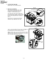
Page 14: ...Installation Use two 5 32 in x 10 mm truss head AA screws and two 5 32 in locking washers BB to screw the bottle opener S to the left side of the side shelf E as shown in Fig 17 13 Battery Installation Unscrew the ignition button housing insert the battery GG into the housing with the positive terminal facing outward Replace the ignition button housing after the battery has been installed as shown...

Page 15: ...6 Liquid Propane Tank Installation Place the liquid propane tank into the hole in the bottom panel and tighten the tank bolt at the back of the grill to secure liquid propane tank as shown in Fig 21 Note Screw the tank bole at the back of grill then insert the 5 32 in x 8mm screw and washer into tank bolt prior to place the liquid propane tank Fig 19 Fig 21 Tank bolt Fig 20 A Q P O R Tank bolt Was...

Page 16: ...the Standard CAN CGA B149 2 installation code for gas burning appliances and equipment and local codes LIQUID PROPANE CYLINDER REQUIREMENTS 20 lb Cylinder A dented or rusty Liquid Propane cylinder may be hazardous and should be checked by your supplier Never use a cylinder with a damaged valve The Liquid Propane cylinder must be constructed and marked in accordance with the specifications for Liqu...

Page 17: ...til it stops 3 Detach the regulator assembly from the cylinder valve by turning the quick coupling nut counterclockwise 4 Place dust cap on cylinder valve outlet whenever the cylinder is not in use Only install the type of dust cap on the cylinder valve outlet that is provided with the cylinder valve Other types of caps or plugs may result in leakage of propane LEAK TESTING GENERAL Although gas co...

Page 18: ...off valve has been located All burners are installed Keep the instruction manual for future reference WARNING 1 Storage of an outdoor cooking gas appliance indoor is permissible only if the cylinder is disconnected and removed from the outdoor cooking gas appliance 2 Cylinder must be stored outdoors out of the reach of children and must not be stored in a building garage or any other enclosed area...

Page 19: ... time However when grilling large pieces of meat or poultry it may be necessary to turn the heat to a lower setting after the initial browning This method cooks the food thoroughly without burning the outside Food cooked for a long time or basted with a sugar based marinade may need a lower heat setting near the end of its cooking time To begin 1 Make sure the grill has been leak tested and is pro...

Page 20: ... substitute regulators If a replacement is necessary contact customer service for proper replacement WARNING Do not use the grill if the odor of gas is present Contact customer service at 1 877 323 5263 TO LIGHT THE MAIN BURNERS 1 Make sure all the knobs are in the OFF position and then turn the Liquid Propane cylinder valve ON by slowly turning counterclockwise 2 Open the lid push and turn the ma...

Page 21: ... not light after several attempts using the control knobs the burners may be lit with a match Main Burner 1 If you have already attempted to light the main burner with the igniter allow 5 minutes for any accumulated gas to dissipate 2 Insert a match into the lighting rod as shown in Fig 24 Ignite the match and insert through the cooking grids to the burner 3 Push and turn Main Burner knob slowly t...

Page 22: ...e Remove the warming rack when using a match to light the rear burner 1 If you have already attempted to light the rear burner with the igniter allow 5 minutes for any accumulated gas to dissipate 2 Insert a match into the lighting rod as shown in Fig 24 Ignite the match and hold next to the burner 3 Push and turn the Side Burner knob slowly to IGNITE HI The burner should light immediately 4 If th...

Page 23: ...over make sure to use other hand to hold cover in place ensuring it doesn t fall and shatter 5 Remove the glass cover from the light bulb housing HINT Use a flathead screwdriver to open it easily Remove the glass cover from the light 6 Use a flathead screwdriver to loosen the four screws locking the bulb in place Loosen but do not remove the bottom two screws under the light first WARNING Keep any...

Page 24: ...Bulb Type Halogen Wattage 10 watts per bulb Voltage 12 volts Please contact customer service at 1 877 323 5263 for assistance on bulb replacement information WARNING Make sure the light switch is in the OFF position and the power plug is disconnected from the power outlet prior to cleaning the glass cover WARNING The light glass cover should not be in contact with water or any other liquid when it...

Page 25: ...n can do the conversion Orifice Chart The different burner valves in this grill have different BTU ratings The holes in the orifices themselves are drilled to different sizes so as to allow the proper amount of gas to flow through them Please note the chart below to give an easy reference for the various orifice opening sizes for the different valves in the grill Orifice Sizes and BTU Ratings LP N...

Page 26: ...he LP regulator from the manifold with a wrench 3 Install the NG regulator hose to the manifold and secure using a wrench 4 Screw the regulator on the right side panel from inside to outside Main Tube Burner Conversion Tools required Phillips Head Screwdriver 6mm nut driver Figure 338 CSA International Project 2075516 27 of 38 ...

Page 27: ...rifices so no additional orifices need to be installed CAUTION The NG orifice is easily loosed or even removed together with the LP orifice when the LP orifice is being unscrewed Make sure the NG orifices are securely installed on the main burner valves after the LP orifices are removed 3 Reinsert tube burners CAUTION Make sure the value with orifice is inserted into the burner venturi Restore the...

Page 28: ...burners 2 Take out the searing side burner from the firebox Locate orifice on end of valve and remove by turning counterclockwise with an 6mm nut driver 3 Insert NG orifice with a 6mm nut driver and secure tightly by turning clockwise Reinsert the searing side burner Side Burner Conversion Tools required Phillips Head Screwdriver 6mm nut driver Figure 338 CSA International Project 2075516 29 of 38...

Page 29: ... by hand 2 Locate orifice on end of valve and remove by turning counterclockwise with a 6mm Wrench Replace with a NG orifice and tighten 3 Replace the side burner pipe and tighten it with a screw drive Put the cooking grid back Rear Burner Conversion Tools required Phillips Head Screwdriver 6mm nut driver Monkey wrench Figure 338 CSA International Project 2075516 30 of 38 ...

Page 30: ...eel There are many stainless steel cleaners available Always use the mildest cleaning process first scrubbing in the direction of the grain Do not use steel wool as it will scratch the surface To touch up noticeable scratches in the stainless steel sand very lightly with dry 100 grit sand paper in the direction of the grain Grease specks can gather and bake onto the surfaces of the stainless steel...

Page 31: ...e Before cleaning make sure the gas supply and control knobs are in the OFF position and the burners have cooled To remove the main burners for cleaning 1 Locate the burner screw at the rear of the firebox 2 Remove the screw and lift the burner out of the firebox To clean the grill burners 1 Clean the exterior of the burner with a wire brush Use a metal scraper for stubborn stains or debris 2 Clea...

Page 32: ...to the burner a Purge the line of any trapped air b Check to see if you can match light the burner c Check to see that the other burners operate normally d Visually check the electrode and wire while pushing the igniter knob If a spark occurs anywhere but the igniter tip the igniter must be replaced Burner flame is yellow and there is a noticeable gas odor 1 Check the burner inlet for obstruction ...

Page 33: ... does not cause difficulty in lighting the grill follow these instructions 1 Make sure all burner valves are OFF 2 Open the tank valve and wait 5 seconds 3 Light the burner one at a time following the lighting instructions listed in the left door and Page 20 Low heat natural gas Gas pressure is affected by gas line and length of gas line from house gas line Follow the recommendations in the chart ...

Page 34: ... warranty MANUFACTURER WILL NOT PAY FOR Service calls to your home Repairs when your product is used for other than normal single family household or residential use Damage resulting from accident alteration misuse lack of maintenance cleaning abuse fire flood acts of God improper installation and installation not in accordance with electrical or plumbing codes or misuse of product Any food loss d...

Page 35: ...mbly 1 52 Main cord 1 16 Top side panel w bracket Left 1 53 Transformer 1 17 Top side panel w bracket Right 1 54 Transformer box assembly 1 18 Front baffle 1 55 Electronic ignite module 1 19 Main gas valve 3 56 Side burner gas valve 1 20 Rotisserie gas valve 1 57 Side burner pipe 1 21 Sear main burner gas valve 1 58 Holder 2 22 Regulator LP 1 59 Side burner bowl assembly 1 23 Side manifold 1 60 Si...

Page 36: ...RAGE QTY REF DESCRIPTION WARRANTY COVERAGE QTY 75 Main burner 3 80 Warming rack 1 76 Sear main burner 1 77 Sear main burner igniter wire 1 78 Flame tamer 3 79 Cooking grid w hole 3 Figure 338 CSA International Project 2075516 37 of 38 ...

Page 37: ...8 24 21 22 03 02 04 05 80 79 78 76 77 74 73 70 72 71 75 69 66 68 67 65 17 64 63 62 60 55 58 58 57 56 29 31 32 35 33 45 44 46 47 43 42 40 37 39 44 41 41 34 48 49 50 51 54 53 52 61 59 36 20 23 38 30 06 07 13 Figure 338 CSA International Project 2075516 38 of 38 ...

Reviews: