13
9.
Left Side Shelf Assembly
Repeat steps 8 for the left side shelf.
10.
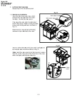
Side Burner Installation
Insert the side burner gas valve, which
extends from the right side of the main
manifold, into the side tube burner
.
Then keep this valve onto the side burner
shelf control panel. Tighten it using two 4mm
screws with locking washers. As shown in
Fig. 14.
Note:The two 4-mm screws with locking
washers are pre-attached to the valve.
Insert a control knob (M) to the valve stem and tighten it
by using the Allen wrench as shown in Fig. 15.
(
Note:
Insert the allen wrench into the hole prior to place
the knob on the valve stem. Place the knob on the valve
stem and tighten with the allen wrench.)
Fig. 14
M
Fig 15
Valve
stem
2 X
Side burner gas valve
Side tube burner
Figure 338
CSA International
Project 2075516
14 of 38


