background image


N560 series H/W Installation Guide 


NexComm Systems, Inc.                                                                                                                24 PAGE


APPENDIX A. Safety Information


A.1 Safety Information Warnings 


Install the equipment only as described in this document. Other manipulations may cause a 

problem to N560 series. 


Never install telephone wiring during a lightning storm. 


Never install telephone jacks in wet locations unless the jack is specifically designed for wet 

locations. 


Use caution when installing or modifying telephone lines. 


User may prepare a proper environment for installing N560 series as specified in the document. 

(temperature, humidity ). 


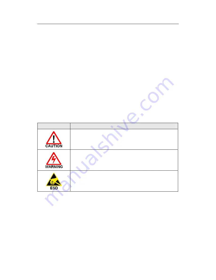
A.2 Symbols 


Symbol 

Description 


Please follow the documented procedures. Otherwise, the equipment is likely 

to be damaged or inoperative. 


Take precaution against a electrical shock. 


The part of the equipment is to be Electro-Static Discharge-sensitive. Pay 

attention to the safety information and procedures.   


Summary of Contents for N560 series H/W

Page 1: ...N560 series H W Installation Guide NexComm Systems Inc 1 PAGE N560 series H W Installation Guide NexComm Systems Inc Tel 82 31 781 1862 Fax 82 31 781 1863 E mail support nexcomm co kr ...

Page 2: ...pied reproduced reduced to any electronic medium or machine readable form or otherwise duplicated and information herein may not be used disseminated or otherwise disclosed except with the prior written consent of NexComm Systems Inc Contact NexComm Systems Inc B 409 Bundang Techno Park 255 Yatap Road Bundang Ku Sungnam City Kyunggi Do 463 760 Korea Tel 82 31 781 1862 Fax 82 31 781 1863 E mail sup...

Page 3: ...ion Guide NexComm Systems Inc 3 PAGE Change Histroy Version Date Effective H W Description Rev 1 0 August 24th 2010 H W versions later than 0 Initial version Rev 1 1 May 6th 2013 H W version later than 1 9 0 Changes of MAX Rate ...

Page 4: ... FX Status LEDs 10 2 4 LAN Port Part 10 100BASE T 10 2 5 2BASE TL Port 11 2 5 1 Connector Part 11 2 5 2 2BASE TL PME Status LEDs 12 3 Installing N560 series 13 3 1 Checking in the Box 13 3 2 Connecting Power to N560 series 14 3 2 1 Connecting 5V DC Power into N560 series 14 3 2 2 Grounding N560 series 15 3 3 Connecting LAN Port to Other Network Devices 15 3 4 Connecting 100BASE FX Port 16 3 5 Conn...

Page 5: ...leshooting N560 series 20 6 Specification 22 6 1 Mechanical Power Requirement 22 6 2 Network Interface 22 6 3 LAN Protocols 22 6 4 Management Interface 22 6 5 VLAN Support 23 6 6 QoS Support 23 6 7 Production Regulatory 23 6 8 Environment 23 A 1 Safety Information Warnings 24 A 2 Symbols 24 APPENDIX B Technical Assistance 25 B 1 NexComm Systems Technical Support 25 B 2 Repair and Return Address 25...

Page 6: ...nt 1 2 Rules of Naming Models N 5 6 x We t t i n g C u r r e n t W supported blank not supported D y i n g G a s p D supported blank not supported 100B FX SFP Port F Support 2 Ports blank not supported 2BASE TL PME 4 supports up to four pairs 2 supports up to two pairs 1 3 List of the Models of N560 series Table 1 1 lists the models of N560 series For convenience of calling N560 series in certain ...

Page 7: ...6x unsupported 2 pairs p0 p3 N562 4 pairs p0 p1 p2 p3 N564 Table 1 1 Models of N560 series 1 4 N560 series Appearance Figure 1 1 shows exterior views of N560 series Note that the appearances of N56xF and N56x are identical Figure 1 1 N560 series Front and Rear View ...

Page 8: ...atus LED This LED shows the status of power supply Table 2 1 summarizes the indication of the LED LED POWER STATUS GREEN ON Normal OFF Power not being connected or abnormal operation of power circuit YELLOW ON DC Adaptor Power Supply Abnormal N5x x D m o d e l o n l y OFF DC Adaptor Power Supply Normal Table 2 1 Indication of Power Status LED 2 1 3 Reset Button This is a button to reset the system...

Page 9: ...ries RS 232 interface provides a RJ 45 female connector Figure 2 2 shows the pin assignments for the console port Console Port RJ 45 Pin outs Pin Signal Description 3 TX Transmit data 5 GND Ground 6 RX Receive data Figure 2 2 Pin Assignments for the Console Port 2 3 SFP Port Part 100BASE FX 2 3 1 Connector Part N56xF have 100BASE FX SFP Module interface provided with an LC type Fiber Optic connect...

Page 10: ... ports These ports of N560 series provide RJ 45 female connectors so a user can use UTP cable with two RJ 45 jacks for the connection In addition each Ethernet port has 2 LEDs so that a user can be aware of the Ethernet ports connectivity One is for link status and RX status the other for TX status Table 2 4 summarizes this LED State Description GREEN OFF LAN port disconnected to the media ON LAN ...

Page 11: ... Models Available Telephone Line Pairs available PMEs N564F N564 4 pairs p0 p1 p2 p3 N562F N562 2 pairs p0 p3 Table 2 5 Available Telephone Line Pairs for Each Model of N560 series Note that each PME uses different pins in the RJ 45 connector p0 uses 4th and 5th pin of the RJ 45 connector p1 uses 7st and 8nd pin of the RJ 45 connector p2 uses 3rd and 6th pin of the RJ 45 connector p3 uses 1th and ...

Page 12: ... Port 2 5 2 2BASE TL PME Status LEDs Figure 2 6 LEDs for Each PME For each 2BASE TL PME N560 series has LEDs showing the status as Figure 2 6 Number attached nearby to the LED is the PME number Table 2 7 2 8 describes the LED s function LED State Description GREEN 0 3 Off Data Link Down or Hand Shaking Slow Blinking Training Fast Blinking Synchronizing On Data Link Up YELLOW S0 Blinking S0 Pair 0 ...

Page 13: ...oose a proper place in which the equipment will operate The surrounding temperature must be in range of 0 40 and high humidity must be avoided Basically N560 series emits a considerable amount of heat User should take care of the N560 series ventilation Do Not stack N560 series or block any slits on the N560 series case Avoid a direct ray of light and electrical interference Do not touch the pins ...

Page 14: ...C adaptor Plug the other end of the power cable into the power terminal 100 240V AC Plug the end of the AC DC power adaptor into the port named 5V DC 3A on the front panel of the N560 series Power LED on the front panel may turn on if the power supply is normal User should be cautious when connecting powers AC power which is plugged into the system directly or into the DC adaptor has to be in appr...

Page 15: ... electrically You may see this ground pin with a symbol depicted here on the rear panel rightmost on N560 series Wire this ground pin between earths ground 3 3 Connecting LAN Port to Other Network Devices Figure 3 4 LAN Port 10 100BASE T Connection Confirm if the UTP cable connector is a RJ 45 jack Connect one end of the UTP cable to the network equipment such as a switch or hub Connect the other ...

Page 16: ...e port named 100BASE FX on the front panel of the N56xF Connect the assembled LC type Fiber Optic connector to SFP Module 3 5 Connecting 2BASE TL Port Figure 3 5 2BASE TL Port Connection 3 5 1 Connecting 2BASE TL Port When making 2BASE TL cable with telephone line pairs be sure that telephone lines are clipped into the RJ 45 connector in the correct order ...

Page 17: ...nutes at most at least about a half minute time taken for sync depends on the state of the line The state of trying sync is called TRAINING and the LED of the PME in this state may blink If the devices synchronized successfully the PME number tagged LEDs may be constantly turned ON 3 6 Connecting Console Port Figure 3 6 Console Cable Connected to N560 series To configure the N560 series the simple...

Page 18: ...lished between the equipment and the other network device Verify that the LAN port s Green LED and Yellow LED are blinking when traffic is flowing into the port traffic being received or out through the port traffic being transmitted respectively 4 3 Checking 100BASE FX connections Verify that SFP Module Fiber Optic lines are connected to a 100BASE FX port Verify that two devices connected with th...

Page 19: ... Password is preliminarily set as password user may change the password refer to the CLI manual User may configure the system with the instruction set provided in the CLI manual NOTE This H W install guide includes 2BASE TL port connection and verifying its function Therefore some basic 2BASE TL port setting commands is provided here Operation on N560 series Command input Setting N560 series as CO...

Page 20: ... operational Console connection disable Verify that the console cable s DB 9 connector and RJ 45 jack is plugged firmly Verify that communication options are correctly set refer to section 5 2BASE TL Port s LEDs OFF with no blinking In normal operation a pair of devices one set as CO the other set as RT 2BASE TL LED will be off if there is no copper pair connected to the port or if a copper pair i...

Page 21: ... traffic on the Ethernet port If the these LED is off and the Network LINK LED is on 1 Verify that there is Ethernet traffic on the network connection 100BASE FX Port s LEDs In normal operation 100BASE FX LED will be off if there is no Fiber Optic connected to the port or if a Fiber Optic is connected at the port but is not connected at an operational remote device 1 Verify that the remote device ...

Page 22: ...ic N56xF only 100BASE FX IEEE802 3u 2 X SFP LC Type connectors SFP MSA SFF 8472 Specification WAN ITU T G 991 2 2004 2BASE TL 64 65o encoding EFM bonding IEEE 802 3ah PAF Dual Interface Over DSL IEEE 802 3 2004 except N560F RJ 45 Connector Max 22 8Mbps 5 7Mbps Port 6 3 LAN Protocols 802 1d Transparent Bridging Up to 8K MAC Address 6 4 Management Interface Console RS 232 RJ 45 Web Browser HTTP SNMP...

Page 23: ...t Ingress Rate control Egress Traffic Shaping Classification based on Port 802 1p DSCP 4 Priority Queues Strict Priority Simple WFQ 6 7 Production Regulatory ISO 9001 Quality Management ISO 14001 Environmental management CE Approval VCCI Approval 6 8 Environment Operating Temperature 0 50 Extended Operating Temperature 40 65 Storage Temperature 40 85 Relative Humidity 98 non condensing ...

Page 24: ...ions unless the jack is specifically designed for wet locations Use caution when installing or modifying telephone lines User may prepare a proper environment for installing N560 series as specified in the document temperature humidity A 2 Symbols Symbol Description Please follow the documented procedures Otherwise the equipment is likely to be damaged or inoperative Take precaution against a elec...

Page 25: ...NexComm Systems Technical Assistance Center phone number is 82 31 781 1862 E mail access to the Technical Assistance Center is available at support nexcomm co kr B 2 Repair and Return Address Before you return a product to NexComm Systems you must obtain a Returned Materials Authorization RMA number from the NexComm Systems Technical Assistance Center The NexComm Systems repair and return address ...

Reviews: