background image

Copyright © 2015 NEXCOM International Co., Ltd. All Rights Reserved.

iii

Contents

VTC 6210-R Series User Manual

WWAN Module Selection Table 
(For Wake-Up & Voice Functions on Mini-PCIe CN26) ........................20
RTC Battery Connector ......................................................................21
Debug 80 Port Connector  .................................................................21
COM1/2 RS232 Connector ................................................................22
COM3 RS232/422/485 Connector .....................................................22
Reset Button (Reserved) .....................................................................23
Power Button Connector (Reserved) ..................................................23
SATA HDD Connector ........................................................................24
Debug Port ........................................................................................24
GAL Download Port ...........................................................................25
GPS Connector ..................................................................................25
Internal WWAN SIM Card Socket (SIM 3) For CN27 ...........................26
MCU Download Port .........................................................................26
Mini-PCIe (USB + PCIe) ......................................................................27
Mini-PCIe (USB) .................................................................................28
Mini-PCIe (USB) .................................................................................29

Chapter 4: System Setup 

Removing the Chassis Cover  ................................................................30
Installing a SSD/HDD Drive ....................................................................31
Installing a WLAN Module .....................................................................33
Installing a WWAN Module ...................................................................33
Installing a SO-DIMM ............................................................................34

Appendix A: Software Demo Utility for I/O Ports of 
Function Control 

Menu Screen .....................................................................................35
1.1  Status  ........................................................................................36
1.2  GPIO Setting ...............................................................................36
1.3  WDT Setting ...............................................................................37

1.4  WWAN Module  .........................................................................37
1.5  Selection of RS-422 or RS-485 for COM3 ...................................37
1.6  Power Off Delay Time  ................................................................38
1.7  Wake Up Function  .....................................................................38
1.8  CAN Bus Setting   .......................................................................39
1.9  Interface Power   ........................................................................39
1.10  Mini-PCIe Power   .....................................................................40

Appendix B: GPS Feature 

uBlox-NEO M8 Overview .......................................................................41
Technical Specifications .........................................................................41

Appendix C: Signal Connection of DI/DO 

GPIO Pinout Description ........................................................................43
SW2 Setting ..........................................................................................43
Digital Input ..........................................................................................44
Digital Output .......................................................................................45

Appendix D: Vehicle Power Management Setup 

Power-on Delay Setting .........................................................................46
Power-off Delay Setting ........................................................................48

Appendix E: Power Consumption..........................50

Summary of Contents for VTC 6210-R Series

Page 1: ...NEXCOM International Co Ltd NEXCOM International Co Ltd Published October 2015 www nexcom com Mobile Computing Solutions Vehicle Telematics Computer VTC 6210 R Series User Manual ...

Page 2: ...Physical Features 1 Front View 1 Rear View 1 Overview 2 Key Features 2 Hardware Specifications 3 Connector Numbering 5 Chapter 2 External Connectors Pinout Description LED Indicators HDD WWAN Power WLAN 6 USB 3 0 Port 6 Reset 7 SIM1 and SIM2 Sockets 7 CFast 8 Line out2 8 Mic2 9 Line out1 9 Mic1 10 LAN1 and LAN2 Ports 10 USB 2 0 Port 11 VGA 11 DisplayPort 12 GPIO CAN 12 DC Input 24 36 110 VDC 13 CO...

Page 3: ...emoving the Chassis Cover 30 Installing a SSD HDD Drive 31 Installing a WLAN Module 33 Installing a WWAN Module 33 Installing a SO DIMM 34 Appendix A Software Demo Utility for I O Ports of Function Control Menu Screen 35 1 1 Status 36 1 2 GPIO Setting 36 1 3 WDT Setting 37 1 4 WWAN Module 37 1 5 Selection of RS 422 or RS 485 for COM3 37 1 6 Power Off Delay Time 38 1 7 Wake Up Function 38 1 8 CAN B...

Page 4: ...has a CE marking For computer systems to remain CE compliant only CE compliant parts may be used Maintaining CE compliance also requires proper cable and cabling techniques Copyright This publication including all photographs illustrations and software is protected under international copyright laws with all rights reserved No part of this manual may be reproduced copied translated or transmitted ...

Page 5: ...Chromium Cr6 0 1 or 1 000ppm Polybrominated biphenyls PBB 0 1 or 1 000ppm and Polybrominated diphenyl Ethers PBDE 0 1 or 1 000ppm In order to meet the RoHS compliant directives NEXCOM has established an engineering and manufacturing task force in to implement the introduction of green products The task force will ensure that we follow the standard NEXCOM development procedure and that all the new ...

Page 6: ...is not responsible for the devices parts Customers are responsible for the safe packaging of defective products making sure it is durable enough to be resistant against further damage and deterioration during transportation In case of damages occurred during transportation the repair is treated as Out of Warranty Any products returned by NEXCOM to other locations besides the customers site will be...

Page 7: ...cian uses parts specified by the manufacturer Avoid using the system near water in direct sunlight or near a heating device The load of the system unit does not solely rely for support from the rackmounts located on the sides Firm support from the bottom is highly necessary in order to provide balance stability The computer is provided with a battery powered real time clock circuit There is a dang...

Page 8: ... must be greater than the voltage and current rating marked on the product All cautions and warnings on the equipment should be noted If the equipment is not used for a long time disconnect it from the power source to avoid damage by transient overvoltage Never pour any liquid into an opening This may cause fire or electrical shock Never open the equipment For safety reasons the equipment should b...

Page 9: ...isit NEXCOM s website at www nexcom com 2 For technical issues that require contacting our technical support team or sales representative please have the following information ready before calling Product name and serial number Detailed information of the peripheral devices Detailed information of the installed software operating system version application software etc A complete description of th...

Page 10: ...No 920 Chung Cheng Rd ZhongHe District New Taipei City 23586 Taiwan R O C Tel 886 2 8226 7796 Fax 886 2 8226 7792 Email sales nexcom com tw www nexcom com tw NEXCOM Intelligent Systems Taichung Office 16F No 250 Sec 2 Chongde Rd Beitun Dist Taichung City 406 R O C Tel 886 4 2249 1179 Fax 886 4 2249 1172 Email sales nexcom com tw www nexcom com tw Japan NEXCOM Japan 9F Tamachi Hara Bldg 4 11 5 Shib...

Page 11: ... Centre Milton Keynes Buckinghamshire MK8 0AB United Kingdom Tel 44 1908 267121 Fax 44 1908 262042 Email sales uk nexcom eu www nexcom eu Italy NEXCOM ITALIA S r l Via Lanino 42 21047 Saronno VA Italia Tel 39 02 9628 0333 Fax 39 02 9625570 Email nexcomitalia nexcom eu www nexcomitalia it NEXCOM Shanghai Room 603 604 Huiyinmingzun Plaza Bldg 1 No 609 Yunlin East Rd Shanghai 200333 China Tel 86 21 5...

Page 12: ...erminal Blocks 2x8 ANYTEK KD161051A000G 3 5mm Male 16P 180D Plug Green 1 3 602DCD1064X00 VTC 6210 R Series DVD Driver VER 1 0 JCL 1 4 5060300058X00 N VTC 6210 RA HDD Mylar S W Mylar Black 1 5 5061500056X00 N VTC 6210 RA Hole Plugs Kang Yang 6x6mm EPDM Black 4 6 4NCPF00314X00 IP67 Power Connector 3 pin ST ST 031 20A Female Screw Diameter 22 2x48 15mm 1 7 603LAN0011X00 LAN Cable for nROK5500 F ST LT...

Page 13: ...ocessor E3845 1 91GHz CPU 2GB DDR3L SO DIMM VGA DP output 2x M12 Giga LAN 2x RS 232 isolation 1x RS 422 485 isolation 8x GPIO isolation 1x M12 two USB 2 0 1x USB 3 0 Type A 24 36VDC Input w o isolation VTC 6210 RF P N 10V00621005X0 Intel Atom processor E3845 1 91GHz CPU 2GB DDR3L SO DIMM VGA DP output 2x M12 Giga LAN 2x RS 232 isolation 1x RS 422 485 isolation 8x GPIO isolation 1x M12 two USB 2 0 ...

Page 14: ...ntroduction VTC 6210 R Series User Manual Chapter 1 Product Introduction Physical Features Front View SSD HDD CFast Line out 2 Mic2 SIM1 SIM2 slot cover LED indicators USB 3 0 Reset Antenna holes GPS Mic1 COM1 COM2 COM3 LAN1 Line out 1 VGA GPIO CAN DisplayPort DC IN LAN2 USB Rear View ...

Page 15: ...dth for a faster data transmission speed Not only data transmission VTC 6210 R Series also supports two way voice communication Equipped with intelligent power management VTC 6210 R Series can be waked on by ignition RTC timer or SMS message remotely By integrating the variety of I O ports and 3x Mini PCIe sockets expansibility VTC 6210 R Series keeps the flexibility to meet the demand for differe...

Page 16: ...ast card socket with cover 1x reset button 1x type A USB 3 0 compliant host supporting system boot up 4x antenna hole for WWAN WLAN BT I O Interface Rear 1x Waterproof DC Input with ignition and 19W typical power consumption optional 24 36 110 VDC 1x M12 w two USB 2 0 compliant host supporting system boot up 2x M12 10 100 1000 Fast Ethernet 1x phone jack 3 5mm for 1x Mic In optional waterproof con...

Page 17: ...erating temperatures 40 C to 70 C w industrial SSD with air flow 10 C to 50 C w commercial HDD with air flow Storage temperatures 40 C to 85 C Relative humidity 10 to 90 non condensing Certifications CE approval FCC Class A EN50155 Certification Ambient Temperature EN 50155 TX 40 70 C Shock and Vibration IEC 61373 class B Interruptions of Voltage Supply Class S1 S2 Supply Change Over Class C1 C2 E...

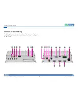
Page 18: ... Reserved 5 Chapter 1 Product Introduction VTC 6210 R Series User Manual Connector Numbering The following diagrams indicate the numbers of the connectors Use these numbers to locate the connectors respective pinout assignments on chapter 2 of the manual ...

Page 19: ...tors Pinout Description LED Indicators HDD WWAN Power WLAN Connector Number 1 LED LED Behavior HDD Light On HDD SSD Active PWR Light On Power On Light Off Power Off WWAN Blinking Active WLAN Blinking Active HDD PWR WWAN WLAN USB 3 0 Port Connector Number 2 Pin Definition Pin Definition 1 5V 2 USB_N 3 USB_P 4 GND 5 USB3_RXN 6 USB3_RXP 7 GND 8 USB3_TXN 9 USB3_TXP 4 1 9 5 ...

Page 20: ...ternal Connectors Pinout Description VTC 6210 R Series User Manual Reset Connector Number 3 Pin Definition 1 GND 2 RESET 1 2 SIM1 and SIM2 Sockets Connector Number 4 Pin Definition Pin Definition C1 UIM1_PWR2 C5 GND C2 UIM1_RST2 C6 NC C3 UIM1_CLK2 C7 UIM1_DAT2 C3 C2 C1 C7 C6 C5 ...

Page 21: ...in Definition Pin Definition S1 GND PC6 NC S2 SATA_TX1 PC7 GND S3 SATA_TX1 PC8 CFAST_LED1_C S4 GND PC9 CFAST_LED2_C S5 SATA_RX1 PC10 NC S6 SATA_RX1 PC11 NC S7 GND PC12 NC PC1 CFAST_CDI PC13 VCC3 PC2 GND PC14 VCC3 PC3 NC PC15 GND PC4 NC PC16 GND PC5 NC PC17 CFAST_CDO Line out2 Connector Number 6 Pin Definition Pin Definition 1 Headphone mono 2 Detect 3 NC 4 Headphone mono 5 GND 6 GND ...

Page 22: ...nectors Pinout Description VTC 6210 R Series User Manual Mic2 Connector Number 7 Pin Definition Pin Definition 1 NC 2 Detect 3 NC 4 Mic In Right Channel to WWAN module 5 GND 6 GND Line out1 Connector Number 8 Pin Definition Pin Definition 22 Left Channel 23 GND 24 Detect 25 Right Channel ...

Page 23: ...onnectors Pinout Description VTC 6210 R Series User Manual Mic1 Connector Number 9 Pin Definition Pin Definition 1 GND 2 Mic In Left Channel 3 GND 4 Detect 5 NC 6 LAN1 and LAN2 Ports Connector Number 10 Pin Definition Pin Definition 1 DA 2 DA 3 DB 4 DB 5 DC 6 DC 7 DD 8 DD 1 8 7 2 3 4 5 6 ...

Page 24: ... VGA Connector Number 12 Pin Definition Pin Definition 1 VGA_RED 2 VGA_GREEN 3 VGA_BLUE 4 VGA_GND 5 VGA_GND 6 VGA_GND 7 VGA_GND 8 VGA_GND 9 VGA 5V 10 VGA_GND 11 VGA_GND 12 VGA_DATA 13 VGA_HS 14 VGA_VS 15 VGA_CLK 5 1 15 11 USB 2 0 Port Connector Number 11 Pin Definition Pin Definition 1 D1 2 D1 3 VCC5 4 GND 5 D2 6 D2 7 VCC5 8 GND 1 8 7 2 3 4 5 6 ...

Page 25: ... GPO4 5 NC 13 GPI1 6 NC 14 GPI2 7 GND 15 GPI3 8 GND 16 GPI4 GPIO can be programmed by S W Please refer to the source code in utility 1 8 GPIO CAN GND Pin 9 Pin 1 Pin 8 Pin 16 DisplayPort Connector Number 13 Pin Definition Pin Definition 1 DP0_DATA0_P 2 GND 3 DP0_DATA0_N 4 DP0_DATA1_P 5 GND 6 DP0_DATA1_N 7 DP0_DATA2_P 8 GND 9 DP0_DATA2_N 10 DP0_DATA3_P 11 GND 12 DP0_DATA3_N 13 CONFIG1 14 CONFIG2 15...

Page 26: ...onnectors Pinout Description VTC 6210 R Series User Manual DC Input 24 36 110 VDC Connector Number 15 Pin Definition 1 Ignition 2 GND 3 Vin 1 3 2 COM1 RS 232 Connector Number 16 Pin Definition Pin Definition 1 DCD_1 2 RXD_1 3 TXD_1 4 DTR_1 5 GND 6 DSR_1 7 RTS_1 8 CTS_1 9 RI 10 NC 1 5 6 9 ...

Page 27: ...ors Pinout Description VTC 6210 R Series User Manual COM3 RS422 485 Connector Number 18 Pin Definition Pin Definition 1 RX 2 RX 3 TX 4 TX 5 GND 1 5 6 9 COM2 RS 232 Connector Number 17 Pin Definition Pin Definition 1 DCD_2 2 RXD_2 3 TXD_2 4 DTR_2 5 GND 6 DSR_2 7 RTS_2 8 CTS_2 9 RI 10 NC 1 5 6 9 ...

Page 28: ...elf before touching any internal components by touching a metal object Static electricity can damage many of the electronic components Humid environment tend to have less static electricity than dry environments A grounding strap is warranted whenever danger of static electricity exists Precautions Computer components and electronic circuit boards can be damaged by discharges of static electricity...

Page 29: ... the jumpers ensure that the jumper caps are placed on the correct pins When the jumper cap is placed on both pins the jumper is short If you remove the jumper cap or place the jumper cap on just one pin the jumper is open Refer to the illustrations below for examples of what the 2 pin and 3 pin jumpers look like when they are short on and open off Two Pin Jumpers Open Left and Short Right Three P...

Page 30: ...Jumpers and Switches VTC 6210 R Series User Manual VTC 6210 R Series Connector Specification Jumper Setting VTC 6210 R Series carrier board placement The figure below is the carrier board used in the VTC 6210 R series system It shows the locations of the jumpers and connectors ...

Page 31: ...1 Normal Clear ME Clear CMOS SW1 1 OFF OFF ON SW1 2 OFF ON OFF Default ON OFF SW2 1 GPO 1 Pull High 5V Open SW2 2 GPO 2 Pull High 5V Open SW2 3 GPO 3 Pull High 5V Open SW2 4 GPO 4 Pull High 5V Open SW2 5 GPI 1 Pull High 5V Open SW2 6 GPI 2 Pull High 5V Open SW2 7 GPI 3 Pull High 5V Open SW2 8 GPI 4 Pull High 5V Open GPIO Pull High Setup Connector location SW2 1 O N 2 1 O N 2 3 4 5 6 7 8 ...

Page 32: ...NEXCOM International Co Ltd All Rights Reserved 19 Chapter 3 Jumpers and Switches VTC 6210 R Series User Manual MiniCard CN26 Power Selection Connector location SW6 3 3V 3 6V SW6 1 OFF ON SW6 2 OFF ON Default 1 O N 2 ...

Page 33: ...erra MC8805 OFF OFF ON OFF HUAWEI EM820W OFF OFF ON OFF Sierra MC7355 OFF OFF ON OFF Telit HE910 OFF OFF ON OFF CM8000 ON OFF OFF ON Sierra MC8090 MC8092 ON OFF OFF OFF Sierra MC9090 OFF OFF ON OFF Default Digital voice is selectable in BIOS WWAN Module Selection Table For Wake Up Voice Functions on Mini PCIe CN26 Connector location SW8 If SMS Ring Wake Up function or and Voice Funciton is are not...

Page 34: ...s RTC Battery Connector Connector size 1 x 2 2 pin header 1 25mm Connector location J9 Pin Definition 1 GND 2 RTC_BAT 1 2 1 10 Debug 80 Port Connector Connector size 1 x 10 10 pin header 1 0mm Connector location J13 Pin Definition Pin Definition 1 GND 2 PCIRST 3 33M_CLK 4 LPC_FRAME 5 LPC_AD3 6 LPC_AD2 7 LPC_AD1 8 LPC_AD0 9 VCC3 10 VCC3 ...

Page 35: ...onnector size 1 x 10 10 pin header 1 00mm Connector location CN32 and CN33 COM3 RS232 422 485 Connector Connector size 1 x 10 10 pin header 1 00mm Connector location CN34 Pin Definition Pin Definition 1 GND 2 GND 3 CTS 4 DSR 5 DTR 6 RXD 7 RI 8 RTS 9 TXD 10 DCD Pin Definition Pin Definition 1 GND 2 GND 3 NC 4 NC 5 TX 6 RX 7 NC 8 NC 9 TX 10 RX 1 10 1 10 ...

Page 36: ...hes VTC 6210 R Series User Manual Reset Button Reserved Connector size 1 x 2 2 pin header 1 25mm Connector location J17 Pin Definition 1 2 Open NORMAL 1 2 Short RESET 1 2 Power Button Connector Reserved Connector size 1 x 2 2 pin header 2 5mm Connector location J20 Pin Definition 1 GND 2 PB 1 2 ...

Page 37: ...N7 1 x 4 4 pin header 2 54mm CN9 1 x 7 7 pin header 1 27mm Connector location CN7 CN9 Pin Definition Pin Definition 1 VCC12 2 GND 3 GND 4 VCC5 Pin Definition Pin Definition 1 GND 2 SATA_TXP0 3 SATA_TXN0 4 GND 5 SATA_RXN0 6 SATA_RXP0 7 GND CN7 CN9 1 4 1 7 1 3 Debug Port Connector size 1 x 3 3 pin header 2 54mm Connector location JP2 Pin Definition 1 TX 2 RX 3 GND ...

Page 38: ...nual GAL Download Port Connector size 1 x 6 6 pin header 2 54mm Connector location JP4 Pin Definition Pin Definition 1 VCC3 2 GND 3 TCK 4 TDO 5 TDI 6 TMS 1 6 6 1 GPS Connector Connector size 1 x 6 6 pin header 1 0mm Connector location J12 Pin Definition Pin Definition 1 GPS_BAT 2 GPS_LED 3 GPS_TX 4 GPS_RX 5 GND 6 VCC3_GPS ...

Page 39: ...l Internal WWAN SIM Card Socket SIM 3 For CN27 Connector location CN24 Pin Definition Pin Definition C1 SIM PWR C5 GND C2 SIM RST C6 NC C3 SIM CLK C7 SIM DAT C5 C6 C7 C1 C2 C3 MCU Download Port Connector size 1 x 5 5 pin header 2 54mm Connector location JP3 Pin Definition Pin Definition 1 V3 3ALW 2 C2D 3 MRST 4 C2CK 5 GND 1 5 ...

Page 40: ... 5S_MINI1 7 CLK_REQ 8 NC 9 GND 10 NC 11 PCIE_CLK 12 NC 13 PCIE_CLK 14 NC 15 GND 16 NC 17 NC 18 GND 19 NC 20 WLAN_DIS 21 GND 22 RESET 23 PCIE_RX_N 24 V3 3A_MINI1 25 PCIE_RX_P 26 GND Pin Definition Pin Definition 27 GND 28 V1 5S_MINI1 29 GND 30 SMBCLK 31 PCIE_TX_N 32 SMBDAT 33 PCIE_TX_P 34 GND 35 GND 36 USB 37 GND 38 USB 39 V3 3A_MINI1 40 GND 41 V3 3A_MINI1 42 NC 43 GND 44 WLAN_LED 45 NC 46 NC 47 NC...

Page 41: ..._N 4 GND 5 MINI_SPK_PRR 6 NC 7 U_GND 8 UIM_PWR2 9 GND 10 UIM_DAT2 11 VCC_MSM26_DIG 12 UIM_CLK2 13 NC 14 UIM_RST2 15 GND 16 NC 17 NC 18 GND 19 NC 20 3 5G_DIS 21 GND 22 3 5G_RST 23 NC 24 V3 3A_MINI_4 25 NC 26 GND Pin Definition Pin Definition 27 GND 28 NC 29 GND 30 NC 31 NC 32 SMS_RI_3 5G_R 33 UMTS_RESET _R 34 GND 35 GND 36 USB 37 GND 38 USB 39 V3 3A_MINI_4 40 GND 41 V3 3A_MINI_4 42 3 5G_LED _R 43 G...

Page 42: ... GND 5 NC 6 1 5V_3 7 PCIE_CLKREQ 2 8 UIM_PWR 9 GND 10 UIM_DATA 11 PCIE_CLKN2 12 UIM_CLK 13 PCIE_CLKP2 14 UIM_RESET 15 GND 16 NC 17 NC 18 GND 19 NC 20 3 5GDIS 21 GND 22 3 5GRST 23 PCIE_RXN2 24 3 3VSB_1 25 PCIE_RXP2 26 GND Pin Definition Pin Definition 27 GND 28 1 5V_2 29 GND 30 SMBCLK 31 PCIE_TXN2 32 SMBDAT 33 UMTS_RESET _R 34 GND 35 GND 36 USB_D 37 GND 38 USB_D 39 3 3VSB_4 40 GND 41 3 3VSB_5 42 LE...

Page 43: ...Chassis Cover Prior to removing the chassis cover make sure the unit s power is off and disconnected from the power sources to prevent electric shock or system damage CAUTION CAUTION CAUTION Front View Rear View 1 The screws on the front and the rear are used to secure the cover to the chassis Remove these screws and put them in a safe place for later use ...

Page 44: ...mb screws on the SSD HDD drive bay and slide the drive bay out 2 Insert the hard drive into the drive bay with the SATA data and power connector facing towards the end Align the hard drive s mounting holes with the mounting holes on the drive bay and use the provided screws to secure the hard drive in place Mounting screws Thumb screws SATA data power connector ...

Page 45: ...t 2015 NEXCOM International Co Ltd All Rights Reserved 32 Chapter 4 System Setup VTC 6210 R Series User Manual 3 Insert the drive bay back in the SSD HDD slot and tighten the thumb screws to secure it in place ...

Page 46: ...ted connector on the edge of the module completely disappears inside the slot Then fasten screws into the mounting holes to secure the module Installing a WWAN Module 1 Locate the WWAN Mini PCI Express slot CN26 CN27 Insert the module into the Mini PCI Express slot at a 45 degrees angle until the gold plated connector on the edge of the module completely disappears inside the slot Then fasten scre...

Page 47: ... 1 Push the ejector tabs which are at the ends of the socket outward Then insert the module into the socket at an approximately 30 degrees angle Apply firm even pressure to each end of the module until it slips down into the socket The contact fingers on the edge of the module will almost completely disappear inside the socket Ejector tab ...

Page 48: ...Appendix A Software Demo Utility for I O Ports of Function Control NEXCOM s software demo utility enables users to test and control different I O port functions on the VTC 6210 R Series This document shows how to use the utility There are also source code files of the utility in the CD Users can refer to the source codes to develop their applications Menu Screen ...

Page 49: ...al of ignition will be shown ON Signal of ignition is high OFF Signal of ignition is low 1 1 2 Battery Status Press the button of Battery Status the status of battery voltage will be shown Low voltage Car battery is at low voltage OK Car battery is not at low voltage 1 2 GPIO Setting 1 2 1 GPIO Select Defines GPIO port as GPO or GPI 1 2 2 GPO Set Selects the GPO ports and makes the output low or h...

Page 50: ...tting Enables or disables the WDT function There are 9 selections of time The timer of WDT can also be cleared by Clear Timer button 1 4 WWAN Module 1 4 1 Mini PCIe CN27 Selects SIM2 or SIM3 card 1 4 2 Mini PCIe CN26 Selects SIM1 or SIM2 card 1 5 Selection of RS 422 or RS 485 for COM3 Enables or disables the power on delay time function There are 8 selections of delay time ...

Page 51: ...lay Time Enables or disables the power off delay time function There are 8 selections of delay time 1 7 Wake Up Function 1 7 1 WWAN Enables or disables the standby power to Mini PCIe socket CN23 for wake up function The wake up function is triggered by external RING or SMS 1 7 2 RTC Enables or disables the RTC wake up function The timer setting of RTC is located in BIOS setting ...

Page 52: ...tatus Reads the connection status of on board CAN2 0B 1 9 Interface Power 1 9 1 USB No 13 Enables or disables the power to USB ports No 13 on rear panel In order to make all input devices such as mouse and keyboard work correctly please do not disable USB No 13 and No 3 at the same time 1 9 2 USB No 3 Enables or disables the power to USB ports No 3 on front panel 1 9 3 GPS Enables or disables the ...

Page 53: ... Reserved 40 Appendix A Software Demo Utility for I O Ports of Function Control VTC 6210 R Series User Manual 1 10 Mini PCIe Power 1 10 1 CN26 Enables or disables the power to USB port on CN26 1 10 2 CN27 Enables or disables the power to USB port on CN27 ...

Page 54: ...l and automotive applications The DDC I2C compliant interface provides connectivity and enables synergies with most u blox cellular modules For RF optimization the NEO M8N Q features an additional front end LNA for easier antenna integration and a front end SAW filter for increased jamming immunity u blox M8 modules use GNSS chips qualified according to AEC Q100 are manufactured in ISO TS 16949 ce...

Page 55: ...T 1 USBV2 0 full speed 12 Mbit s 1 SPI optional 1 DDC I2 C compliant Digital I O Configurable timepulse 1 EXTINT input for Wakeup Timepulse Configurable 0 25 Hz to 10 MHz Protocols NMEA UBX binary RTCM Package 24 pin LCC Leadless Chip Carrier 12 2 x 16 0 x 2 4 mm 1 6 g NEO M8 Top View 1 2 3 4 5 6 7 8 9 10 11 12 24 22 21 20 19 18 17 16 15 14 13 23 GND Reserved D_SEL TIMEPULSE EXTINT USB_DM USB_DP V...

Page 56: ...GPIO Pinout Description SW2 Setting GPO1 GPO2 GPO3 GPO4 GPI1 GPI2 GPI3 GPI4 VCC5 PO DIP SW 2X8 PO SW2 DIP SW 2X8 1 2 3 4 5 6 7 8 14 13 12 11 10 9 15 16 330Ω GPIO SW2 On Pull up VCC5 Off Don t Care GPIO SW2 SW2 1 SW2 8 Pull up VCC5 Default Settings 1 8 GPIO CAN GND OBDII Pin 9 Pin 1 Pin 8 Pin 16 Pin Definition 9 GPO1 10 GPO2 11 GPO3 12 GPO4 13 GPI1 14 GPI2 15 GPI3 16 GPI4 ...

Page 57: ...l up resistor to 5V internally The figure below shows how to connect an external output source to one of the input channel External Internal GPO1 GPI1 GPI2 GPO2 GPI3 GPO4 GPI4 GPO3 GPIO_GND CN14 9 10 11 12 13 14 15 7 16 VCC5 6 11 5 12 4 13 1K 1K External Internal GPO1 GPI1 GPI2 GPO2 GPI3 GPO4 GPI4 GPO3 GPIO_GND CN14 9 10 11 12 13 14 15 7 16 Resistor External power External Switch Port GPI Register...

Page 58: ...ds for output signal type The output signal has two states one is low level driven to 0V from GPO signal other is open high voltage is provided from external device Wet Contact default The SW2 needs to switch to ON state The GPO signal will have a pull up resistor to 5V internally when you switch SW2 to ON state The output signal has two states one is low level driven to 0V from GPO signal other i...

Page 59: ...Delay Setting Disable Power on Delay Advanced Version 2 14 1219 Copyright C 2010 American Megatrends Inc Aptio Setup Utility Copyright C 2010 American Megatrends Inc Select Screen Select Item Enter Select Change Opt F1 General Help F2 Previous Values F3 Optimized Defaults F4 Save Exit ESC Exit Power Management Configuration Delay Time Setting Power On Delay Power Off Delay Disable Disable ...

Page 60: ...F4 Save Exit ESC Exit Power On Delay Setting Power Management Configuration Delay Time Setting Power On Delay Power Off Delay Enable Disable Power On Delay Disable Enable Advanced Version 2 14 1219 Copyright C 2010 American Megatrends Inc Aptio Setup Utility Copyright C 2010 American Megatrends Inc Select Screen Select Item Enter Select Change Opt F1 General Help F2 Previous Values F3 Optimized De...

Page 61: ... F4 Save Exit ESC Exit Power Management Configuration Delay Time Setting Power On Delay Power Off Delay Disable Disable Advanced Version 2 14 1219 Copyright C 2010 American Megatrends Inc Aptio Setup Utility Copyright C 2010 American Megatrends Inc Select Screen Select Item Enter Select Change Opt F1 General Help F2 Previous Values F3 Optimized Defaults F4 Save Exit ESC Exit Delay Off Delay Settin...

Page 62: ...tility Copyright C 2010 American Megatrends Inc Select Screen Select Item Enter Select Change Opt F1 General Help F2 Previous Values F3 Optimized Defaults F4 Save Exit ESC Exit Delay Off Time Selection Setting Power Management Configuration Delay Time Setting Power On Delay Power Off Delay Delay Off Time Selection Disable Enable 20 sec Delay On Time selection 20 sec 01 min 05 min 10 min 30 min 01 ...

Page 63: ...ion 6 0 Device 2G DDR3L and SSD Idle Mode Burn in Mode S3 S4 S5 0 43A 24V 0 58A 24V 0 16A 24V 0 009A 24V 0 009A 24V 10 32W 13 92W 3 84W 0 2W 0 2W Item 2 OS Windows 8 Burn in Software Version 6 0 Device 8G DDR3L SSD CFast GPS OBDII module WWAN CAN 2 0B module WLAN Bluetooth card capture card Idle Mode Burn in Mode S3 S4 S5 N A 0 69A 24V 0 16A 24V 0 009A 24V 0 009A 24V N A 16 56W 3 84W 0 2W 0 2W ...

Reviews: