


Copyright © 2015 NEXCOM International Co., Ltd. All Rights Reserved.
44
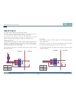
Appendix C: Signal Connection of DI/DO
VTC 6210-R Series User Manual
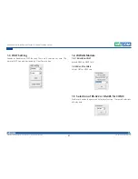
Dry Contact:
Digital Input
CN15 connector for GPI signal (digital signal input)
The CN15 has 4 digital input channels.
Wet Contact (default)
The GPI signals have a pull up resistor to 5V internally.
The figure below shows how to connect an external output source to one
of the input channel.
External
Internal
GPO1
GPI1
GPI2
GPO2
GPI3
GPO4
GPI4
GPO3
GPIO_GND
CN14
9
10
11
12
13
14
15
7
16
VCC5
6
11
5
12
4
13
1K
1K
External
Internal
GPO1
GPI1
GPI2
GPO2
GPI3
GPO4
GPI4
GPO3
GPIO_GND
CN14
9
10
11
12
13
14
15
7
16
Resistor
External power
External
Switch
Port
GPI
Register
ON (Short)
GND
0
OFF (Open)
OPEN
1
External
Switch
Port
GPI
Register
ON (Short)
GND
0
OFF (Open)
HIGH
1


