


Copyright © 2015 NEXCOM International Co., Ltd. All Rights Reserved.
43
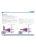
Appendix C: Signal Connection of DI/DO
VTC 6210-R Series User Manual
a
PPendIx
C: s
IGnal
C
onneCtIon
of
dI/do
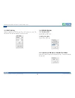
GPIO Pinout Description
SW2 Setting
GPO1
GPO2
GPO3
GPO4
GPI1
GPI2
GPI3
GPI4
VCC5
PO
DIP SW 2X8
PO
SW2
DIP SW 2X8
1
2
3
4
5
6
7
8
14
13
12
11
10
9
15
16
330Ω
GPIO (SW2)
On
Pull up VCC5
Off
Don’t Care
GPIO (SW2)
SW2.1~SW2.8
Pull up VCC5
Default Settings:
1
8
GPIO
CAN
GND
OBDII
Pin 9
Pin 1
Pin 8
Pin 16
Pin
Definition
9
GPO1
10
GPO2
11
GPO3
12
GPO4
13
GPI1
14
GPI2
15
GPI3
16
GPI4


