background image

Copyright © 2013 NEXCOM International Co., Ltd. All Rights Reserved.

vii

NCb-231 User Manual 

Preface

Warnings

Read and adhere to all warnings, cautions, and notices in this guide and 
the documentation supplied with the chassis, power supply, and accessory 
modules. If the instructions for the chassis and power supply are inconsistent 
with these instructions or the instructions for accessory modules, contact 
the  supplier  to  find  out  how  you  can  ensure  that  your  computer  meets 
safety and regulatory requirements. 

Cautions

Electrostatic  discharge  (ESD)  can  damage  system  components.  Do  the 
described  procedures  only  at  an  ESD  workstation.  If  no  such  station  is 
available,  you  can  provide  some  ESD  protection  by  wearing  an  antistatic 
wrist strap and attaching it to a metal part of the computer chassis. 

Safety Information

Before installing and using the device, note the following precautions: 


Read all instructions carefully. 


Do not place the unit on an unstable surface, cart, or stand. 


Follow all warnings and cautions in this manual. 


When  replacing  parts,  ensure  that  your  service  technician  uses  parts 
specified by the manufacturer. 


Avoid using the system near water, in direct sunlight, or near a heating 
device. 


The  load  of  the  system  unit  does  not  solely  rely  for  support  from  the 
rackmounts located on the sides. Firm support from the bottom is highly 
necessary in order to provide balance stability. 


The network camera is provided with a battery-powered real-time clock 
circuit. There is a danger of explosion if battery is incorrectly replaced. 
Replace  only  with  the  same  or  equivalent  type  recommended  by  the 
manufacturer.  Discard  used  batteries  according  to  the  manufacturer’s 
instructions.

Installation Recommendations

Ensure you have a stable, clean working environment. Dust and dirt can get 
into  components  and  cause  a  malfunction.  Use  containers  to  keep  small 
components separated. 

Adequate  lighting  and  proper  tools  can  prevent  you  from  accidentally 
damaging  the  internal  components.  Most  of  the  procedures  that  follow 
require only a few simple tools, including the following: 


A Philips screwdriver 


A flat-tipped screwdriver 


A grounding strap 


An anti-static pad 

Using your fingers can disconnect most of the connections. It is recommended 
that you do not use needle-nose pliers to disconnect connections as these 
can damage the soft metal or plastic parts of the connectors.

Summary of Contents for NCb-231

Page 1: ...NEXCOM International Co Ltd NEXCOM International Co Ltd Published May 2014 www nexcom com Intelligent Digital Security IP Camera NCb 231 User Manual ...

Page 2: ...llation 3 Chapter 2 Camera Configuration Accessing the Camera s Configuration Menu Graphical User Interface 4 Installing IP FINDER 4 IP FINDER 7 Web Browser Internet Explorer 9 Configuring the Camera s Setting 10 Browsing Through the Configuration Menu 11 Video 12 Video Stream 12 Stream 1 12 Stream 2 13 Stream 3 13 Camera Settings 14 Image Adjustments 14 Mirror Flip 15 Wide Dynamic Range WDR 15 Ca...

Page 3: ...nagement 33 SD Card Information 33 File List 33 Date Time 34 Current Camera Time 34 Time Settings 34 Date Time Format 35 NTP Server 35 Firmware Upgrade 36 Firmware Version 36 Update 36 Maintenance 37 Maintain 37 Camera Name Settings 37 DC Iris Calibration 37 Advanced Settings 38 Video 39 Camera Settings Advanced 39 Chroma Sharpness Suppression 39 Manual White Balance 39 Manual Exposure Gain 39 Cam...

Page 4: ...e Detection 48 Tampering Detection 49 Settings 49 Event Actions Advanced 50 When Motion Detection Triggered 50 When Tampering Detection Triggered 50 System 51 Schedule Recording 51 Schedule Recording Setting 51 COM Port 52 RS 232 Control 52 RS 485 Control 52 Chapter 3 Viewing Live Video via VLC Media Player 53 ...

Page 5: ...COM International Co Ltd All other product names mentioned herein are registered trademarks of their respective owners Regulatory Compliance Statements This section provides the FCC compliance statement for Class B devices and describes how to keep the system CE compliant Declaration of Conformity FCC This equipment has been tested and verified to comply with the limits for a Class B digital devic...

Page 6: ...lybrominated diphenyl Ethers PBDE 0 1 or 1 000ppm In order to meet the RoHS compliant directives NEXCOM has established an engineering and manufacturing task force to implement the introduction of green products The task force will ensure that we follow the standard NEXCOM development procedure and that all the new RoHS components and new manufacturing processes maintain the highest industry quali...

Page 7: ...s parts specified by the manufacturer Avoid using the system near water in direct sunlight or near a heating device The load of the system unit does not solely rely for support from the rackmounts located on the sides Firm support from the bottom is highly necessary in order to provide balance stability The network camera is provided with a battery powered real time clock circuit There is a danger...

Page 8: ...the equipment is not used for a long time disconnect it from the power source to avoid damage by transient overvoltage 10 Never pour any liquid into an opening This may cause fire or electrical shock 11 Never open the equipment For safety reasons the equipment should be opened only by qualified service personnel 12 If one of the following situations arises get the equipment checked by service pers...

Page 9: ...ion of the installed software operating system version application software etc A complete description of the problem The exact wordings of the error messages Warning 1 Handling the unit carry the unit with both hands and handle it with care 2 Maintenance to keep the unit clean use only approved cleaning products or clean with a dry cloth Conventions Used in this Manual Warning Information about c...

Page 10: ...Copyright 2013 NEXCOM International Co Ltd All Rights Reserved x NCb 231 User Manual Preface Package Contents The NCb 231 package contains the following accessories Screw Kit Quick guide User Manual ...

Page 11: ...o Ltd All Rights Reserved 1 NCb 231 User Manual Chapter 1 Product Introduction Chapter 1 Product Introduction Overview Key Features LPC box camera Full HD1080P 30fps 2 3 Image sensor Global shutter Support 20 C 60 C 4 F 140 F Lens optional ...

Page 12: ...io Output Line out Network Interface 10 100 1000 Mbps Ethernet RJ 45 Supported protocols HTTP TCP IP UDP RTP RTSP FTP SMTP DHCP DNS DDNS NTP uPnP ONVIF IPv4 v6 Security Multi level passwords HTTP encryption I O Connector Audio in out Port 2x 3 5mm phone jack D I O 2x DI 2x DO RS485 Yes Micro SD slot Yes RJ45 Yes RS232 Yes Flash Strobe Out Yes event trigger IR LED Strobe Out Yes Frequently Reset Bu...

Page 13: ...International Co Ltd All Rights Reserved 3 NCb 231 User Manual Chapter 1 Product Introduction Physical Descriptions Light Sensor Lens Cover Aluminum Focus Ring Iris Connector Lens Purchased Separately DI O Pinout Assignment ...

Page 14: ...network subnet before proceeding You can access the camera via a web browser or NexCam Assistant software included with the camera The following information outlines the instructions for each method Installing IP FINDER 1 Locate the installation file IP FINDER Setup msi on the CD 2 Once located double click on the file to start the installation program 3 Click the Next button on the welcome screen...

Page 15: ...click on the Browse button and locate the desired installation folder Next button Browse button Disk Cost button User accounts 7 Click on the Next button to continue 5 To check the available drives you can install the software to and their available and required disk space please click on the Disk Cost button 6 Specify which user accounts on the computer can access the program the options are Ever...

Page 16: ...eserved 6 NCb 231 User Manual Chapter 2 Camera Configuration Next button 8 Click on the Next button to begin installation Close button 9 Once the installation process is complete click on the Close button to finish A shortcut will be created on the desktop ...

Page 17: ... menu via Internet Explorer You can also access the menu by double clicking the camera s IP address under Camera List 2 When the program is launched it will begin searching the network for the IP camera automatically the search will last for up to 90 seconds You can also manually search cameras by clicking on the Search button 3 Once the camera is discovered it will show the following information ...

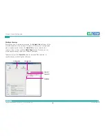
Page 18: ...cameras on the network To access all the cameras configuration menu simultaneously click on the Select All button to select all the cameras in the list then click the Home Page button Similarly you can access specific ones by ticking the camera s checkbox To deselect press the Clear All button to remove all the selection or specific ones by unchecking the checkbox Home Page Camera List Select All ...

Page 19: ...Enter button 3 You will be prompted with a pop up window asking for login information type in admin default login name and 9999 default password 4 Once logged in you will see the main screen with video stream stream 3 Web Browser Internet Explorer Snapshot Takes a image snapshot from the camera you will be prompted to store the image file onto the computer s hard drive Start Stop Press to stop the...

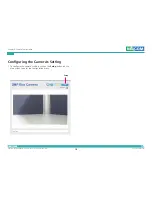
Page 20: ...al Co Ltd All Rights Reserved 10 NCb 231 User Manual Chapter 2 Camera Configuration Configuring the Camera s Setting 1 To configure the camera s setting click on the Setup button on the main screen to enter the configuration menu Setup ...

Page 21: ...on the left hand side of the interface clicking it will open their corresponding sub menu on the right The following are the camera settings available on the left hand side Video Video Stream Camera Settings Overlay Settings Privacy Mask Network TCP IP FTP SMTP Ports Events Motion Detection Alarm In Out Trigger Event Actions System Audio Settings Recording Settings User Management SD Card Manageme...

Page 22: ... mode as VBR variable bit rate or CBR constant bit rate for the stream Target Bit Rate If the Bit Rate Control is set to CBR you can manually set the bit rate in this field the range is 30 20000kbit s GOP Length Configures the GOP length of the stream The options are 0 5 1 2 3 and 4 setting 0 5 seconds will yield the best video quality Video Video Stream This section configures the settings of the...

Page 23: ...Bit Rate If the Bit Rate Control is set to CBR you can manually set the bit rate in this field the range is 30 10000kbit s GOP Length Configures the GOP length of the stream The options are 0 5 1 2 3 and 4 setting 0 5 seconds will yield the best video quality Stream 3 Resolution Displays the resolution of the video stream FrameRate Adjusts the frame rate of the video stream Setting 0 will disable ...

Page 24: ...image the range is 0 255 with 0 being the lowest contrast Press the button to decrease the value or button to increase the value The default value is 128 Color Saturation Configures the color saturation of the image the range is 0 255 with 0 being the lowest saturation Press the button to decrease the value or button to increase the value The default value is 128 Sharpness Configures the sharpness...

Page 25: ...isables WDR function to activate at the specified time You can configure the Start Time and End Time in 24 hour format Use Mode During Scheduled Hours Selects the WDR constrast level to use during the scheduled time Use Mode Outside of the Scheduled Hours Selects the WDR constrast level to use outside of the scheduled time Mirror Flip Enable Mirror Flip the camera image horizontally Enable Flip Fl...

Page 26: ...oor daylight Incandescent Adjusts the white balance for indoor light Fluorescent Adjusts the white balance for fluorescent light Exposure Exposure Mode This option configures the anti flickering function of the camera If the image is suffering from flickering under fluorescent light selecting Auto will allow the camera to automatically adjust the light frequency to match the current fluorescent li...

Page 27: ...e in the camera is too dark Day Night Configures the day and night mode of the camera Auto Allows the camera to automatically sense the current lighting level and determine what type of color range it should display Forced Color Forces the camera to display color regardless of the current lighting level Forced Black White Forces the camera to display black white images regardless of the current li...

Page 28: ... on the bottom right corner Enable Text Enables or disables the Viewer to display text on the upper right corner The text displayed can be configured in the field box Display Camera Name Enables or disables the Viewer to display the camera s name on the upper left corner The name displayed can be configured in the Maintenance menu For information on Maintenance menu please refer to page 37 Save Sa...

Page 29: ... Chapter 2 Camera Configuration Privacy Mask This section configures which area of the live video in Viewer will be masked for privacy A total of 3 privacy masks can be configured Settings Privacy Mask Color Selects the color of the privacy mask The available colors are Black and White ...

Page 30: ...o mask by holding down the mouse button and drag to make a rectangular square release the button once the desired area is covered 3 Press the Setting Area button in Enable mask zone 1 to set this area as mask 4 You will see the selected area turn black or white depending on which color was chosen This example uses black as the mask color Rectangular square Mask area 5 To create the second and thir...

Page 31: ... an IP address select this option and input the IP address subnet mask default gateway primary and secondary DNS server address Enable IPv6 To manually configure an IPv6 address select this option and input the IPv6 address Current Network Settings Displays the current IP address subnet mask default gateway primary and secondary DNS server address of the camera Save Save button to apply the config...

Page 32: ... Username Specify the login username for the FTP server Password Specify the login password for the FTP server Test Remote FTP Server Server Status Displays the status of the test connection FTP Test Tests the network connection between the camera and FTP server Save Save button to apply the configurations click on this button once all the settings are confirmed for the new changes to take effect ...

Page 33: ...ogin username for the SMTP mail server Password Specify the login password for the SMTP mail server Email Address From Specify the email address of the sender To Mail Address Mail Address Specify the email address to send the email when an event is triggered by motion detection Mail Test Status Displays the status of the test connection Mail Test Tests the network connection between the camera and...

Page 34: ... menu RTSP Stream 1 to 3 RTSP Port Configures the RTSP port number of stream 1 to 3 and displays the URL of stream 1 to 3 The range is 554 1025 65535 Default URL of Stream 1 rtsp cameraIP 554 live stream1 Default URL of Stream 2 rtsp cameraIP 8556 live stream2 Default URL of Stream 3 rtsp cameraIP 8555 live stream3 Save Save button to apply the configurations click on this button once all the sett...

Page 35: ...eo in Viewer will be monitored for detecting motion Settings Enable Motion Detection Enables or disables motion detection function Sensitivity Configures the sensitivity of motion detection the sensitivity determines the amount of motion required to trigger an event the range is 1 to 100 with 1 being the least sensitive For more information on event please refer to Event Actions on page 28 ...

Page 36: ... specify the sensitivity level 2 In the live video screen below select the desired area for motion detection by clicking on the rectangular box The border of the box will turn red indicating that it is selected You can select multiple boxes up to 5x5 boxes can be selected 3 Press the Save button once all the desired areas are selected for the changes to take effect Highlighted box Area with motion...

Page 37: ...cted to the alarm output1 and alarm output2 The options are Low and High Alarm Out Control Alarm Out Mode and Alarm Out 2 Mode Specify the alarm out mode the options are User Mode and Event Mode When User Mode is selected the alarm output will be triggered based on user configurations When Event Mode is selected the alarm output will be triggered based on the configurations set in Event Actions Fo...

Page 38: ...on configuring the FTP server please refer to FTP on page 22 Send Email Notification Check this option to send an email notifying the event for more information on configuring the email address please refer to SMTP on page 23 Alarm Output and Alarm Output2 Check this option to activate the device connected to alarm output and alarm output2 when motion detection is triggered When Alarm In Triggered...

Page 39: ...ore information on configuring the email address please refer to SMTP on page 23 Alarm Output and Alarm Output2 Check this option to activate the device connected to alarm output and alarm output2 when alarm in is triggered Save Save button to apply the configurations click on this button once all the settings are confirmed for the new changes to take effect Reset Reset button to discard all the s...

Page 40: ...dio in on the camera When enabled specify the volume in the Audio In Volume textbox The range is 1 100 Audio Out Enable Enables or disables audio out on the camera When enabled specify the volume in the Audio Out Volume textbox The range is 1 100 Save Save button to apply the configurations click on this button once all the settings are confirmed for the new changes to take effect Reset Reset butt...

Page 41: ... to configure the recording settings of the IP camera AVI File Setting Stream Source Selects which video stream number to record the options are Stream 1 and Stream 2 Save Save button to apply the configurations click on this button once all the settings are confirmed for the new changes to take effect Reset Reset button to discard all the settings applied ...

Page 42: ...a description for the account under the User Information field Access Level Administrator Has full control read write over every configuration menu item Operator Has full control read write over every configuration menu item in Video and Event only Viewer Only has access read to the live view of the camera main screen User List Displays user accounts available on the camera to edit an account s pa...

Page 43: ...talled this section will display information on the availability of the SD card and the percentage of the total storage used Format Formats the SD card all data stored on the SD card will be erased if this option is used SD Card Overwrite Enables or disables overwrite protection for the SD card Press the Save button to apply the setting File List Displays the information of the folders and files s...

Page 44: ...option to synchronize the date and time with a NTP server Synchronize with Computer Time Select this option to synchronize the date and time to the computer connected to the camera Manually Setting Select this option to manually configure the date and time Time Zone Select the time zone relevant to your location in the drop down list Daylight Saving Select this option to enable daylight saving The...

Page 45: ...DD MM YYYY Time Format Configures the format that the time will be displayed in The options are 12Hrs and 24Hrs NTP Server NTP Server Address If Synchronize with NTP Server is selected as the time mode type in the host name or IP address of the NTP server Save Save button to apply the configurations click on this button once all the settings are confirmed for the new changes to take effect Reset R...

Page 46: ...the current firmware version Update Specify the Firmware Image File to Upgrade To update the camera s firmware click on the Browse button and locate the firmware image file once the file is selected press the Update button to begin CAUTION CAUTION CAUTION The firmware update process will take around 15 minutes to complete during this time do not disconnect the network cable reset or power off the ...

Page 47: ...fy a name for the camera The name will be displayed in the upper left corner on the live video stream of the camera To enable this make sure the option Display Camera Name in the Overlay Settings menu is checked For information on the Overlay Settings menu please refer to page 18 DC Iris Calibration To calibrate the DC Iris lens check the option Choose to use DC Iris Lens and press the DC Iris Cal...

Page 48: ...ings This section is used to configure advanced settings of the IP camera The following are the advanced settings available on the left hand side Video Camera Settings ROI AE Weights Network DDNS SNMP Multicast Events Ethernet Lost Detection Face Detection Tampering Detection Event Actions System Schedule Recording Basic Settings ...

Page 49: ... captures Manual White Balance Note To adjust the white balance manually please set the White Balance Mode to Off in Basic Settings R G Gain Adjusts the warm white balance the range is 0 0 4 0 from yellow to red B G Gain Adjusts the cold white balance the range is 0 0 4 0 from green to blue Manual Exposure Gain Note To adjust the exposure and gain manually please set the Exposure Mode to Locked in...

Page 50: ...rol Auto Iris When enabled the DC Iris will adjust the opening automatically based on the lighting levels in the environment Manual Iris Control Enables manual control of the iris there are 4 control options to choose from Full Open Opens the iris to the maximum aperture Full Close Closes the iris to the smallest aperture Step Open Opens the iris according to the step levels specified in the Step ...

Page 51: ...eduled time Use Mode Outside of the Scheduled Hours Selects the IR cut filter control mode to use outside of the scheduled time Gamma Control Default Activates the default gamma state Gamma Adjusts the gamma manually the range is 0 01 1 00 with 0 01 being the lowest value Color Filter Remove Red Adds red filters to the camera s view Remove Green Adds green filters to the camera s view Remove Blue ...

Page 52: ... instructions below illustrate how to setup 5 ROI zones 1 To create ROI zone 1 check the Enable ROI zone 1 and on the live video screen select the area to set the ROI by holding down the mouse button and drag to make a rectangular square release the button once the desired area is covered 2 Press the Setting Area button in Enable ROI zone 1 to set this area as the ROI 3 Repeat the above steps to c...

Page 53: ... 1 2 On the live video screen select the area by holding down the mouse button and drag to make a rectangular square release the button once the desired area is covered 3 Press the Setting Area button in Enable Regional weighting 1 4 Configure the weighting value in the corresponding textbox the range is 0 10 5 Repeat the above steps to create auto exposure weightings for zones 3 to 5 To delete an...

Page 54: ...DNS service provider from the drop down list the available providers are Dyn NO IP dnsExit and DtDNS Web Site URL link to the selected DDNS service provider s web site Username Username of the DDNS account Password Password of the DDNS account Hostname Hostname of the DDNS account Internet IP Address Displays the IP address assigned when the connection is established Manual Used to manually specif...

Page 55: ...MP v1 v2 Enables or disables SNMPv1 and SNMPv2 support Read Community Used to configure the read community string Write Community Used to configure the write community string Traps for SNMP v1 v2 Enable Traps Enables the IP camera to send SNMP trap messages Trap Address Specifies the IP address of the trap server to receive the trap messages Trap Community Used to configure the trap community stri...

Page 56: ... the multicast group RTP Port Configures the RTP port of the multicast address this port is used for streaming video and audio data RTCP Port Configures the RTCP port of the multicast address this port is used for controlling RTP streams Path Configures the URL address of the video stream Always Multicast Check this option to enable the video stream to start multicast streaming without using RTCP ...

Page 57: ...Detection This page is used to configure link failure detection for Ethernet Settings Enable Ethernet Lost Detection Enables link failure detection of the Ethernet connection Alarm Output and Alarm Output2 Enables the camera to trigger the device connected to alarm output and alarm output2 upon detecting failure of the Ethernet connection ...

Page 58: ... the button once the desired area is covered 2 Press the Setting Area button to set this area for face recognition To delete the area press the Remove button Threshold Configures the sensitivity of the face recognition the range is 1 9 with 1 being the least sensitive Detect Direction Configures the direction to detect faces Up Detect faces on the top 90 degrees from the front Right Detect faces o...

Page 59: ...ection is used to configure tamper detection settings Settings Enable Tampering Detect Enables or disables tamper detection When enabled the camera will trigger actions enabled in the Event Actions menu upon detecting image blurs Sensitivity Configures the sensitivity of the tamper detection the range is 1 100 with 1 being the least sensitive ...

Page 60: ...mation on configuring the email address please refer to SMTP on page 23 Alarm Output and Alarm Output2 Check this option to activate the device connected to alarm output and alarm output2 when face detection is triggered When Tampering Detection Triggered Save Stream to SD Card Check this option to store the video stream onto the SD card Select the desired file format in the drop down menu the opt...

Page 61: ...etting Enable Schedule Recording Enables or disables recording of the video stream Daily Configures the camera to record at the specified Start Time and End Time Weekly Configures the camera to record on the specified day and time of the week S Select this to set full day recording D Select this to cancel full day recording E Displays the end time of the recording clicking E will allow you to conf...

Page 62: ... network the range is 1025 65535 Baud Rate Data Bit Parity Stop Bit Flow Control Configures the serial settings baud rate data bit parity stop bit and flow control Please make sure the serial settings match the RS 232 device s serial settings RS 485 Control Port Configures the port number to access the RS 485 device connected to the COM port over the network the range is 1025 65535 Direction Baud ...

Page 63: ... network please follow the instructions below 1 Locate and open VLC media player 2 Go to Media Open Network Stream 3 Enter the following RTSP URL rtsp 192 168 1 168 554 live stream1 Note RTSP URL of stream 1 similarly you can view stream 2 and 3 of the camera by entering their corresponding URLs Please refer to Ports on page 24 for more information on the URL link 4 Press the Play button to start ...

Reviews: