Fire Bird V ATMEGA2560 Hardware Manual
Pin No.
Pin Name
Description
1
Servo POD1
Connection with ATMEGA2560 ADC channel 14
2
Servo POD2
Connection with ATMEGA2560 ADC channel 15
3
GPIO
Connection with ATMEGA2560 OC2A/PB4 pin (Pin no. 23)
4
Atmega8 ADC
Connection with ATMEGA8 ADC channel 1
5
Atmega8 ADC
Connection with ATMEGA8 ADC channel 3
6
Ground
Ground
7
V SYS
+ 5V (VCC)
8
V BATT
Battery Voltage(9V – 11V)
Table 3.22: Servo Pod socket pin description
3.19.6 Microcontroller Board Jumpers
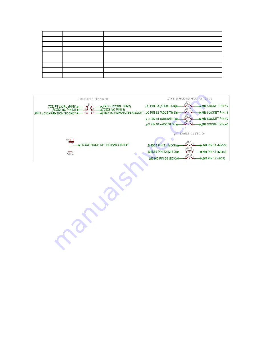
Figure 3.66: Jumpers schematic
Microcontroller board has 4 jumpers labeled from J1 to J4 as shown in Figure 3.58 and figure
3.66.
J1:
Jumper J1 is used to select between the UART2 pins connections of ATMEGA2560 on the
uC Expansion Socket and to the onboard FT232 USB to serial converter circuit. When jumper is
in position as shown in the figure 3.66, it enables the onboard USB communication through
UART2 (default state).
J2:
When J2 is on IR Proximity sensors 1 to 4 are connected to the ADC pins of the
ATMEGA2560. When J2 is open, same ADC pins can be used for JTAG on the uC expansion
socket or as ADCs for external sensor interfacing. In the default state J2 is on.
J3:
If J3 is on, all the pins of the PORT J are connected to the LED bargraph display. It can be
used for quick message display for debug purpose. If J3 is off, LED connection is disabled. All
the pins of the PORT J are available on the uC expansion socket for use as GPIOs. In the default
state J3 is kept on.
J4:
When J4 is on, SPI bus between ATMEGA2560 (master) and ATMEGA8 (slave) is
connected and you can access date from the slave microcontroller. Since SPI lines are also used
for In System Programming (ISP) to load firmware on the master and slave microcontroller via
SPI port you need to remove all jumpers from J4 before attempting ISP. J4 is kept open as
default setting.
© NEX Robotics Pvt. Ltd. and ERTS Lab, CSE, IIT Bombay, INDIA 70


