


Fire Bird V ATMEGA2560 Hardware Manual
Figure 3.42: Potentiometers for white line sensor calibration
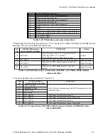
Figure 3.43: White line sensor pin connections (White line Sensor Board)
Figure 3.44: White line white line sensor connector pin configuration on main board
Pin No.
Function
1
White line sensor 1 (Left sensor) Data Out
2
White line sensor 1 LED via potentiometer
3
White line sensor 2 (Center Sensor) Data Out
4
White line sensor 2 LED via potentiometer
5
White line sensor 3 (Right sensor) Data Out
6
White line sensor 3 LED via potentiometer
7
White line sensor 4 Data Out
8
White line sensor 4 LED via potentiometer*
© NEX Robotics Pvt. Ltd. and ERTS Lab, CSE, IIT Bombay, INDIA 51