


Fire Bird V ATMEGA2560 Hardware Manual
3.18 Wireless communication adaptor
Figure 3.57 shows location of the socket for the wireless module. It supports XBee and XBee Pro
series 1 and series 2 ZigBee wireless modules from digi international, RN-XV WiFi to serial
module and Bluetooth module. Table 3.20 shows the functions of the status indicator LEDs for
the XBee wireless modules.
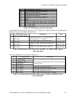
Figure 3.56: ZigBee wireless module schematics
Figure 3.57: ZigBee wireless module and LED indicators
LED
Connection to XBee Wireless
module Pin no.
Description
ASSO
15
Associate LED
RSSI
6
RX Signal Strength Indicator
Table 3.20: XBee wireless module LED functions
Important:
You can change XBee wireless module’s frequency and Pan ID, so that multiple XBee wireless
modules can coexist at the same time. For more information on this, refer to “Application Notes”
folder which is located inside the “Manuals and Application notes” folder in the documentation
CD.
© NEX Robotics Pvt. Ltd. and ERTS Lab, CSE, IIT Bombay, INDIA 65