background image

XPS-RL 

Quick Start 

When all stages are added to the stages.ini file, build the system using the web tool 

Manual Configuration

” under the main tab “

System

”. In this tool, the stages get 

assigned to positioners and the positioners get assigned to motion groups. Please refer to 

chapter 6.3 (in the XPS-RL User's Manual) for details on the different motion groups 

and their specific features. The group name and positioner name can be any user given 

name. Once the system has been built, all system information is stored in a file called 

system.ini. Also, the system.ini file is located in the Config folder of the XPS-RL 

controller and can be viewed or edited from the Web Tool text editor under “

Files

 → 

Configuration


files

”. 

 
The following describes the different steps needed to add a stage, to modify the stage 

parameters and to build a manual configuration. Chapter 4.0 in the XPS-RL User's 

Manual provides further information about some of the steps described here. 
Once you are logged in as Administrator, click on “

Stages” 

and then click on “

Add, 

remove or edit stages

”. 

1.


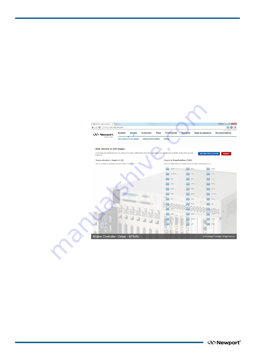
The following screen appears: 


2.


Click on the family name from the Stages in StageDataBase list and a pop up 

window appears. 

3.


Click the part number corresponding to your hardware. 

4.


Select the driver (corresponding to your hardware) and configuration. 
For all continuous rotation stages, you can choose between a “regular” stage 

configuration and a “Spindle” configuration. A Spindle is a specific rotary device 

(no indexing) with a periodic position reset at 360° (by default), meaning 360° 

equals 0°. When defining the stage as Spindle in the stages.ini, you must assign this 

stage also to a Spindle group in the system configuration and vice versa. For details 

about Spindles, please refer to section 6.3 in the XPS-RL User's Manual. 
For some stages, you can choose between “regular” initialization or LMI (Large 

Move Initialization). The LMI method produces a larger movement of the stage for 

commutation and could be used if “regular” initialization fails. 

5.


The box “

Use ESP Compatibility for Hardware detection

” is checked by default. 

If your stage has an ESP chip inside (see the ESP-compatible sticker on the stage) 

EDH0367En1021 — 12/17


22  

Summary of Contents for XPS-RL

Page 1: ...XPS RL Universal High Performance Motion Controller Driver Quick Start...

Page 2: ...he above warranties do not apply to products which have been repaired or modified without Newport s written approval or products subjected to unusual physical thermal or electrical stress improper ins...

Page 3: ...4 2 Power ON 7 2 5 Connecting to the XPS RL 7 2 5 1 Straight Through Cables Black 7 2 5 2 Cross Over Cables Gray 8 2 5 3 Direct Connection to the XPS RL Controller 8 2 5 4 Connecting the XPS RL to a...

Page 4: ...XPS RL Quick Start 3 0 XPS RL Controller Driver Documentation 27 Service Form 29 EDH0367En1021 12 17 iv...

Page 5: ...trade secrets to any other person firm organization or employee that does not need consistent with Customer s right of use hereunder to obtain access to the Newport Programs and Related Materials Thes...

Page 6: ...order number Description of problem Environment in which the system is used State of the system before the problem Frequency and repeatability of problem Can the product continue to operate with this...

Page 7: ...he XPS RL Controller Driver system it is important that users become thoroughly familiar with available documentation The XPS RL Quick Start is delivered as a hard copy with the controller The XPS RL...

Page 8: ...eries Controller Driver This symbol indicates a hazard arising from dangerous voltages Any mishandling could result in damage to the equipment personal injury or even death 1 2 3 European Union CE Mar...

Page 9: ...ed during all phases of operation of this equipment Failure to comply with these precautions or with specific warnings elsewhere in this manual violates safety standards of design manufacture and the...

Page 10: ...ontroller Driver unit Do not use liquid or aerosol cleaners Do not open the XPS RL Controller Driver stand alone motion controller There are no user serviceable parts inside the XPS RL Controller Driv...

Page 11: ...ct the contents for damage If there is visible damage to the equipment upon receipt inform the shipping company and Newport Corporation immediately WARNING Do not attempt to operate this equipment if...

Page 12: ...my stage hence once communication to the controller is established the controller is usable To access full functionality of the controller stages must be connected 2 4 1 Proper Ventilation Figure 6 In...

Page 13: ...Connecting to the XPS RL XPS RL supports 10 100 1000 Mbps Ethernet networking 1 Direct connection PC to XPS RL The DHCP server active on the Ethernet plug identified REMOTE will automatically configu...

Page 14: ...ction between a PC and the XPS RL controller you need to use the crossover cable and the REMOTE connector at the back of the XPS RL Figure 9 Direct connection to the XPS RL using cross over cable REMO...

Page 15: ...the Ethernet card address is set to Obtain an IP address automatically This procedure is for the Windows 7 operating system almost similar process for Windows 8 1 Start Button Control Panel Network a...

Page 16: ...ler Following is the procedure for connecting to the controller 5 Open Internet Browser and connect to http 192 168 254 254 Login Username Administrator Password Administrator Please see the picture b...

Page 17: ...sub menu IP management The Static IP address the Netmask value and the Gateway IP address must be provided by your Network Administrator to avoid network conflicts Once you have these addresses you ca...

Page 18: ...o Section 2 6 Configuring the Controller 2 5 5 Configuring the XPS RL for Connection to a Corporate Network Using Dynamic IP Configuration It is recommended to ask your IT department to configure the...

Page 19: ...P is displayed above In case the XPS RL cannot negotiate an IP address from the DHCP the displayed address will be 0 0 0 0 In that case contact your IT department Remove the REMOTE cable and if needed...

Page 20: ...know the new assigned one by the DHCP NOTE Do not use Dynamic IP configuration if your DHCP server uses Windows NT 4 0 2 5 6 Recovering a lost IP configuration If you want to recover a lost IP configu...

Page 21: ...tor Please see the picture below Role Administrator NOTE Please note that the login text is case sensitive Once you are logged in you can change the IP configuration by following the steps described i...

Page 22: ...ion quick configuration and manual configuration Default configuration is the simplest method to configure the controller but has some limitations Default configuration works only with Newport ESP com...

Page 23: ...ion The following screen appears If you want to continue click the OK button and the following page appears Check if all connected stages are recognized by the system To change the Group name type in...

Page 24: ...nd its reference position When done the state number is 11 and the action button changes to disable Enter an allowed position value in the Absolute move 1 field and click GO The stage moves to this ab...

Page 25: ...the stages ini file with the needed configurations using Add remove or edit stages under the main tab Stages see chapter 2 6 3 When logged in as Administrator select System then Quick configuration T...

Page 26: ...ller To add stage parameters to the stages ini file click on Stages then click Add remove or edit stages If all stages are recognized and after selecting the stage parameters click APPLY REBOOT and th...

Page 27: ...ternal database which contains parameters for all Newport stages and stores these parameters in a file called stages ini Hence the stages ini file contains the parameters for only a subset of stages a...

Page 28: ...strator click on Stages and then click on Add remove or edit stages 1 The following screen appears 2 Click on the family name from the Stages in StageDataBase list and a pop up window appears 3 Click...

Page 29: ...o make changes NOTE From this screen you have access to all stage parameters Only experienced users should modify these parameters For the exact meaning of the different parameters please refer to App...

Page 30: ...The other fields refer to the error compensation mapping of the XPS RL controller see chapter 10 0 for details For the first configuration don t enter anything in these fields 11 Enter the appropriat...

Page 31: ...r motion groups 15 When done click on APPLY AND REBOOT to complete the system configuration The controller re boots and the following message appears Click on PROCEED When the controller has finished...

Page 32: ...tions please read the rest of this manual 2 6 4 Manual Configuration for non Newport stages To configure the XPS RL controller to stages or positioning devices not made by Newport use the tool Create...

Page 33: ...matical explanations Compensation backlash linear error correction positioner XY XYZ mapping Event triggers event actions examples Data gathering internal and external Triggers position compare output...

Page 34: ...anguages Downloading Documentation In order to provide user s access to the most actual documentation the User s Manual Programmer s Manual and the Software Drivers Manual are only supplied as softwar...

Page 35: ...______________________________________________________________________________________________________ _________________________________________________________________________________________________...

Page 36: ...mail tech newport com Service RMAs Returns Tel 800 222 6440 e mail service newport com Europe MICRO CONTROLE Spectra Physics S A S 9 rue du Bois Sauvage 91055 vry CEDEX France Sales Tel 33 0 1 60 91 6...

Reviews: