


56
The following paragraphs explain the PID components and their operation.
7.5.2
P Loop
Starting with the simplest type of closed loop control, the
P
(proportional) loop. The
diagram in Figure 19 shows its configuration.
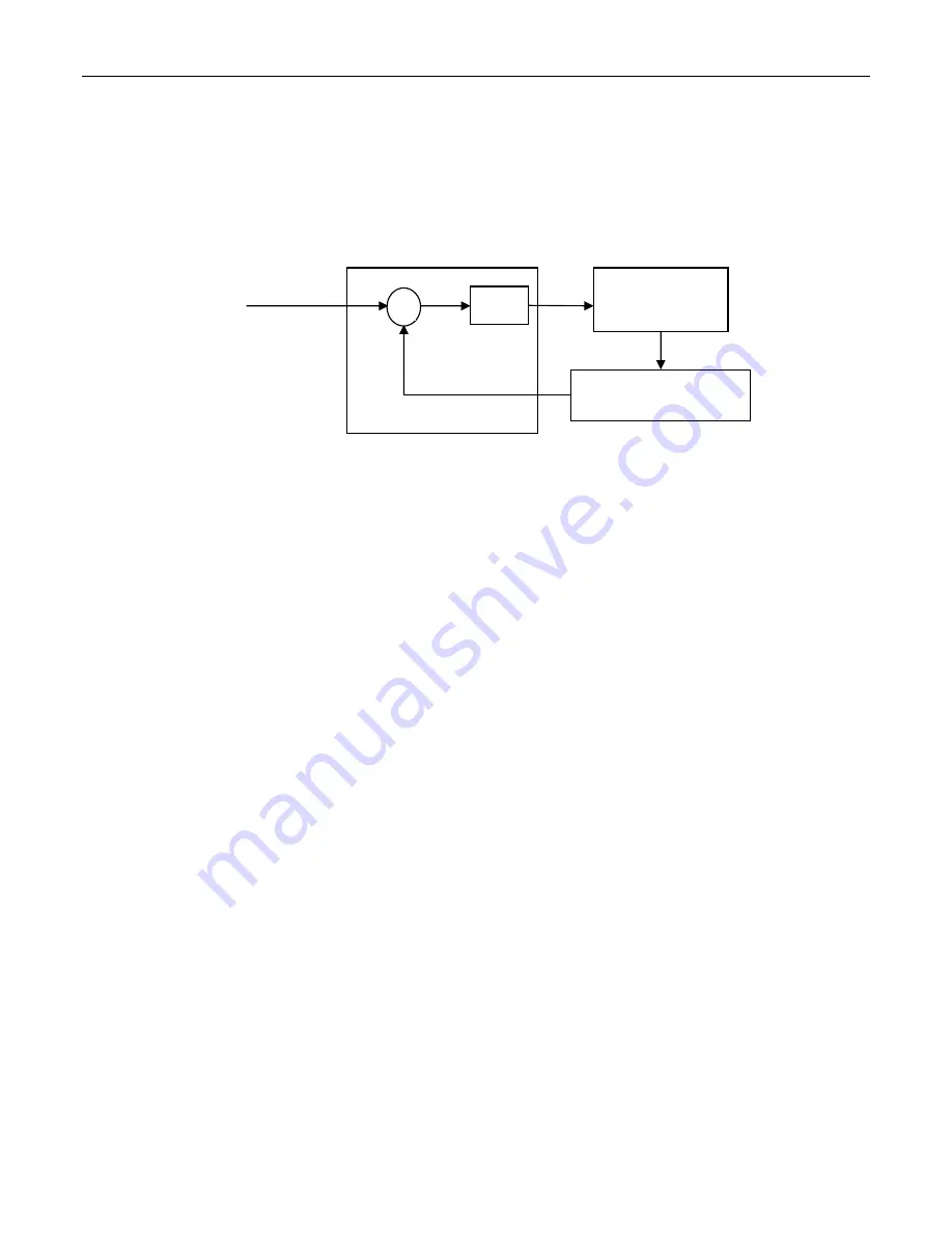
Figure 19
Proportional Temperature Controller Block Diagram
The controller continuously compares the actual temperature, as reported by the
temperature sensor, to the desired temperature (setpoint). The difference
e
is the
temperature following error. It amplifies this error (by multiplying it with
K
p
) and
generates a control signal (current) that drives the TE module.
There are a few conclusions that could be drawn from studying this block diagram:
The control signal is
proportional
to the temperature following error.
There must be a following error in order to drive the TE module.
Small errors cannot be corrected if they do not generate enough current for the TE
module to overcome any thermodynamic effects from the mounts.
Increasing the
K
p
gain reduces the necessary following error but too much of it will
generate instabilities and oscillations.
u
Temperature
Setpoint
Temperature
Controller
Thermo-Electric
(TE) Module
Temperature Sensor
+
-
x
K
p
e
Summary of Contents for 350B
Page 2: ...Temperature Controllers User s Manual Model 350B ...
Page 7: ...vi This page is intentionally left blank ...
Page 11: ...x This page is intentionally left blank ...
Page 25: ...24 Getting Started This page is intentionally left blank ...
Page 31: ...30 System Operation This page is intentionally left blank ...
Page 61: ...60 ...