P.O. Box 1306
Newport Beach
California 92663
Phone: 714-751-0488
Fax: 714-957-1621
E-Mail: [email protected]
www.newmartelecom.com
1
4
3
2
5
6
9
8
7
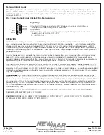
Ignition OUT
Ignition IN
Charge/Discharge
Not Used
Not Used
Not Used
Not Used
Not Used
- INPUT
4
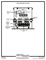
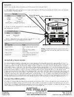
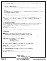
Motorola Output Signals:
The MDP is programmed to provide early warning signals to mobile data computers designed for this input (such as
Motorola® MW 800 Series workstations and video recording system cameras .) Interface signals for this output is located
on the D-sub 9 pin connector per the following pin out (please contact factory for mating connector with pigtails, part
number 425-5233-0):
Signal Key:
1) Ignition OUT: to be connected to MDT interface with signal which initiates
startup and shutdown sequence of computer.
2) Ignition In
3) Charge/Discharge Signal: used to signal computer that power is coming from
back-up battery. Active LOW (<2V)
4) - Input: Ground
OPERATION
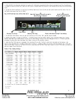
Under normal operating conditions, the electronics operate from primary battery voltage of the vehicle or vessel. This
same voltage powers the internal battery charger that maintains the MDP internal battery in a fully charged state. The
charger circuit operates on an input range of 10.2 - 15.5 volts, so even if the primary battery voltage decays the MDP
internal battery will receive proper voltage and be maintained at full charge. The internal charger has a rapid recovery,
three step output and temperature compensation sensor that varies the charge voltage based on ambient temperature to
prolong battery life.
A fast acting sense circuit connects the internal battery online to the electronics any time when the input voltage drops
below 10.5 volts or total interruption of voltage occurs augmenting voltage to the electronics for 3 seconds. If proper
primary voltage is not restored within the 3 second time frame, input from the vehicle battery disconnects and electronics
operate entirely from the MDP reserve battery (see settings sections for variations on this function).
The internal MDP battery will continue to supply power until primary vehicle or vessel battery voltage is restored (> 12.0
volts) or to the point where the MDP internal battery discharges below 9.6 volts, at which time a low voltage disconnect
energizes, shutting off all power to the MDP output. When primary vehicle or vessel voltage is restored, the internal battery
will begin to recharge and be available for reserve power after voltage is restored to >13.5 volts (approx 120 minutes from
fully discharged state)
Important Note:
The MDP function is that of an uninterruptable power source, so if electronics are wired directly to the
MDP output and the primary feed voltage to the MDP is via an ignition switch, when the switch is turned off the MDP will
continue to power the load until its internal battery reaches a low voltage disconnect point. Ideally the power to the MDP
should be left on. If the vehicle is left for an extended period, the powered electronics should be shut off to conserve the
primary battery. The MDP has a power conservation “sleep mode” that initiates and turns off the 3 stage charger when
the unit senses float charge for more than 20 minutes. For long term storage, remove loads from MDP output and remove
input and battery fuses.
CAUTION:
DO NOT LEAVE THE BATTERY DISCHARGED FOR EXTENDED PERIODS OF TIME. IT MAY BE PERMANENTLY
DAMAGED AND MAY NOT TAKE A RECHARGE
.
CAUTION:
IF RE-INSTALLING FUSES AFTER VEHICLE BEING ‘OUT OF SERVICE’, ALLOW FOR 2 HOURS TO CHARGE THE
INTERNAL BATTERY BEFORE MDP IS PUT INTO SERVICE.
Fig. 2: Input/Output Signals (D-Sub 9 Pin) - Motorola Apps.


