21
15272 Newsboy Circle
Huntington Beach,
CA 92649
Phone: 714-751-0488
Fax: 714-372-7930
E-Mail: [email protected]
PoweringTheNetwork.com
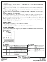
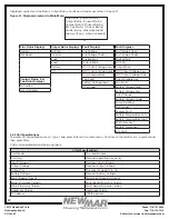
5.6.8 System Setting
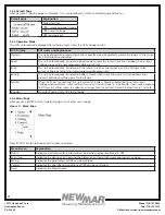
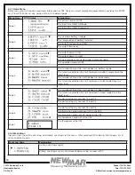
To access System Setting menu, type 4 and press Enter on the main menu. To return to the main menu, press Esc and then
press Enter buttons.
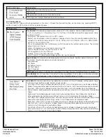
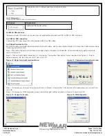
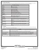
Following table lists all options in system setting.
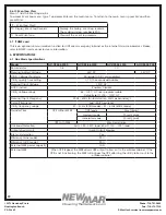
4 – System Setting
40. Ext Fan On By Temperature
Setting temperature in °C to trigger external cooling fan. When temperature is higher
than setting, battery power will be provided for external cooling fan. The temperature
can be set from 20 to 55°C with 1°C increment by each increase. The factory default
temperature is 25°C.
41. Battery Low Voltage
Voltage level for low battery alarm. For AC-UPS-48-1200, AC-UPS-48-1500 and AC-
UPS-48-2000, the voltage level can be configured from 42V DC to 55V DC. The factory
default setting is 46V DC. For AC-UPS-24-700, the voltage level can be configured from
21V DC to 27.5V DC. The factory default setting is 23V DC.
42. Charging Current
Setting battery charging current. It can be configured to 2A, 4A, 6A, 8A or 10A. The
factory default value is 10A.
43. Battery Temperature
Compensation
Setting charging rate based on the battery case temperature. The factory default
value is -3mv/°C /Cell. It can be configured to -2.5, -3, -3.5 or -4 mv/°C /Cell.
44. Test Timer
Setting time duration for self-test. The factory default setting is 1 minute. It can be
configured from 1 to 255 minutes.
45. Backup Timer
Setting backup time. The factory default setting is 120 minutes. It can be configured
from 0 to 480 minutes with 15-minute increment of each increase.
46. Set To Default Ups
Set all the configurations to factory default value.
47. Set Date
Adjust the date.
48. Set Time
Adjust the time.
49. Change Password
Change password. The factory default password is 1111. Note: The password can only
be changed in Line mode.
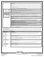
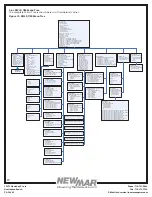
5.6.9 Line Conditioning Setup
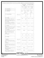
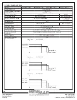
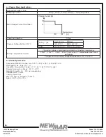
This option allows the user to change various detection and warning levels for input AC voltages, qualified and
unqualified values, transfer & re-transfer setting points for going in & out of Battery mode, Boost or Buck modes. See the
detailed descriptions in the following Parameter Description table.
The UPS uses line conditioning to operate at maximum efficiency under specific standard supply voltage. Buck and boost
voltage regulator is an ideal solution when the line voltage is consistently higher or lower than nominal. The transformer
can buck (decrease) or boost (increase) the supply voltage without battery backup or involving other active UPS board
level components.
When activated, the transformer will automatically switch to the secondary tap to buck or boost voltage 10% to keep the
output voltage within acceptable range.
CAUTION: Improper parameter value setting can cause permanent damage to the unit. Changes should only be made
by qualified and trained personnel.
Note: Parameter values are interdependent. Changing one value can affect the range and permissible value(s) in other
fields. This feature is to avoid users entering contradictory values.
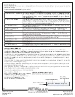
Users can change parameters as following procedure.
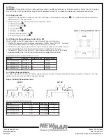
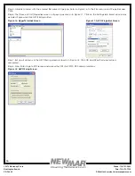
Step 1: Go to the Menu 5.
Step 2: When Parameter Change Screen appears
(Figure 22), type the new value within
acceptable range and press Enter. The screen
will return to the Line Slow Detection
Screen. For example, refer to Figure 22.
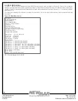
Low Limit [088] Enter new value. (088->120)
>_
Name of Parameter
Current Parameter Status
Acceptable
Parameter Limits
Prompt
Figure 22: Parameter Change Screen
(Slow Detect Low Limit Screen Shown)

