- 3 -
- 12 -
USER'S MANUAL
This symbol is intended to alert the user to the presence of
uninsulated
“dangerous voltage” within the product’s enclosure that may be of sufficient
magnitude to constitute a risk of electric shock to persons.
This symbol is intended to alert the user to the presence of important
operating and manintenance(servicing)instructions in the literature
accompanying the appliance.
RISK OF ELECTRIC SHOCK
DO NOT OPEN
WARNING
TO REDUCE THE RISK OF ELECTRIC SHOCK, DO NOT REMOVE COVER
(OR BACK). NO USER-SERVICEABLE PARTS INSIDE. REFER SERVICING
TO QUALIFIED SERVICE PERSONNEL.
CAUTIONS
NEVER REMOVE THE BACK COVER
Removal of the back cover should be carried out only by qualified personnal.
DO NOT USE IN HOSTILE ENVIROMENTS
To prevent shock or fire hazard, do not expose the unit to rain or moisture. This unit
is designed to be used in the office or home. Do not subject the unit to vibrations,
dust of corrosive gases.
KEEP IN A WELL VENTILATIED PLACE
Ventilation holes are provided on the cabinet to prevent the temperature from rising.
Do not cover the unit or place anything on the top of unit.
AVOID HEAT
Avoid placing the unit in direct sunshine or near a heating appliance.
TO ELIMINATE EYE FATIGUE
Do not use the unit against a bright back ground and where sunlight or other light
sources will shine directly on the monitor
BE CAREFUL OF HEAVY OBJECT
Neither the monitor itself nor any other heavy object should rest on the power cord.
Damage to a power cord can cause fire or electrical shock.
5. SYSTEM OPERATION
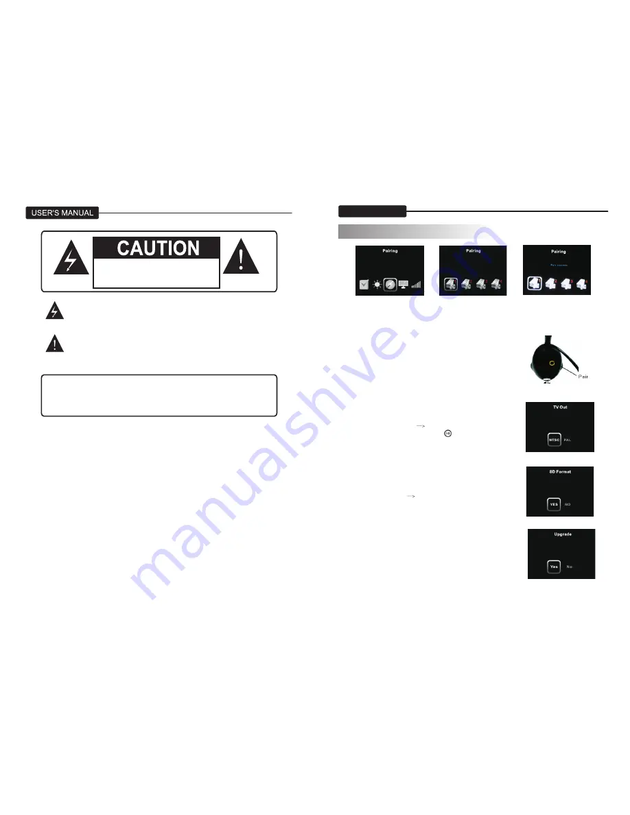
4. A message will be dispalyed on the receiver screen. The receiver will count down
from 10 to 0 you must press the “pair” button on the camera during this time
to successfully pair the camera.
If the button on the camera is not pressed, the receiver will display” Pair Fail” and
no pairing will take palce.
5. press the “pair” button on the back
of the camera in 10 seconds.
5.5 AV output
(1). Use the specific output cable,
(2). Enter “SYSTEM SETUP”
“TV output”
(3). Select “PAL” or “NTSC”, then press” ” and then select
“yes” to confirm.
(4). Press the “AV” button to transfer the signal to
anther monitor.
(5). Press the “AV” button again to return LCD display.
5.6 Format SD card
Enter “SYSTEM SETUP”
“SD format”, select “yes” to
Confirm formatting the SD card.
* Caution: All the data will be delete after format
the SD card.
5.7 Firmware Upgrade
(1). Copy the upgrade program to the root of the
SD card.
(2) Insert the SD card in the SD card slot.
(3) Enter “SYSTEM SETUP”/ “Upgrade”, then select
“YES” to perform the upgrade.
(4). Reboot the machine after upgrade finished.
Summary of Contents for WL24MNK
Page 2: ......


