.
Press button to select” SINGLE/QUAD/AUTO” display mode.
ON:valid channel
OFF:invalid channel
SINGLE
QUAD
4. INSTALLATION GUIDELINE
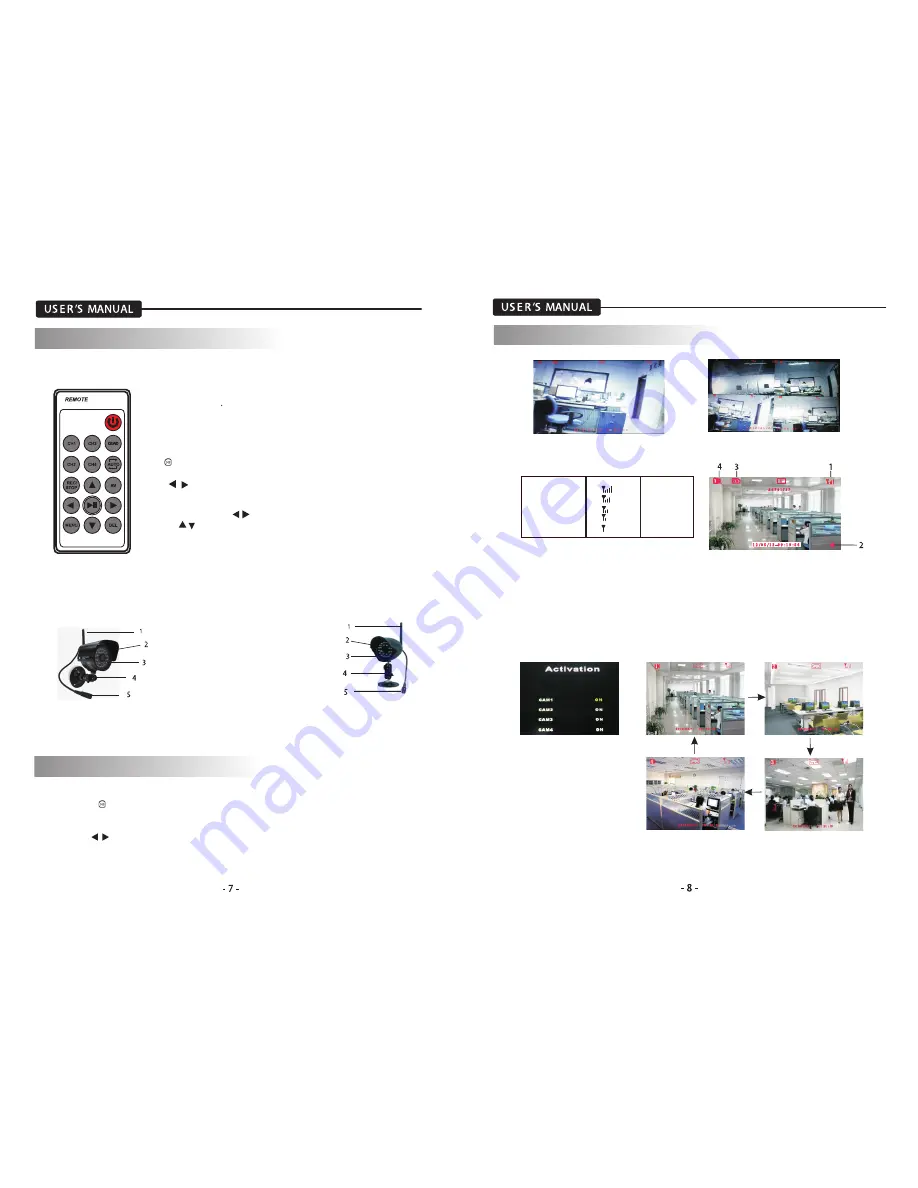
4.2 Remote control
2) CH1-CH4 Button: single image view mode.
1) Power Button: Power on/off the display screen.
3) Quad Button: Quad image view mode.
4) Auto Button: Press to enter auto sequencing mode(CH1~CH4).
5) REC/STOP Button: Press to enter or exit recording mode.
6) AV Button: Press to output audio/video. When outputting audio
and video, the LCD screen will be switched
t
o black. Press AV button
again to return LCD display mode.
7)
Button: Play or pause the selected file under “PLAYBACK/VIDEO”
menu .
Press to select SINGLE/QUAD/AUTO display mode
8/9) Button:
In the on-screen menu, press to select setting item.
In playback mode, use the buttons to fast-forward or rewind
In single mode, press button to select CH1/ CH2/ CH3 /CH4.
10/11) button:
In the on-screen menu, use the bottons to scroll up or down.
In live or playback mode, use the buttons to increase the volume.
12) Menu button: press to enter or exit to the Main-menu.
13) DEL Button: Press to delect Unnecessary files
4.3 Camera Overview
1. Camera Antenna: Sends signals to the
receiver or receives
signal from the receiver.
2. Lens: Catches the video in front of the
lens and transmits video
from camera to receiver.
3. IR LED
4. Bracket: Use the bracket to mount the
camera on a wall or
other flat surfaces.
5.DC power supply socket.
5. SYSTEM OPERATION
5.1 Live Display
5.1.1
Manual channel selection
Press “ ” button to view each channel(CH1~CH4) individually in SINGLE mode.
5. SYSTEM OPERATION
(1). signal indicator-- The signal indicator shows the strength of its singal being of the camera.
(2). Recording Indicator—when the receiver is recording, the red indicator REC will be shown
on the LCD screen.
(3). SD card indicator—when a SD card is inserted into the SD card slot, the indicator will be
shown on the LCD screen.
(4). Channel indicator—Displays the current channel number. Press the “CH1/ CH2/ CH3 /CH4”
button on the remote control to switch between available cameras.
5.1.2 Auto switching mode
The switching channels are set in menu”Camera Setup/ Activation”
5.2 Recording Mode
The system is designed for SD card recording. You can manually, scheduled record the video.
Signal indicator:
Signal Strength Indecator
warning
Perfect
None
Good
None
Fair
Low signal
Low
Low signal
No Signal
No signal
Summary of Contents for WL24MNK
Page 2: ......


