P l e a s e G i v e P a r t N o . , D e s c r i p t i o n a n d U n i t S e r i a l N o .
HIGHWAY EQUIPMENT COMPANY
25
97372-B
Page Rev. A
INSTALLATION INSTRUCTIONS CONTINUED
Securing Spreader Body to Frame
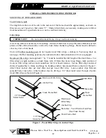
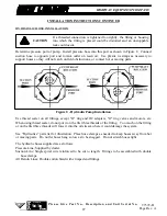
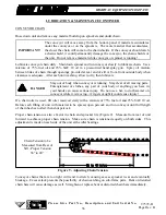
Install mounting angles and tighten mounting bolts to recommended torque. Weld mounting angles to
spreader cross tubes by welding on front, outer and rear sides (Figure 4). Make sure welds between
mounting angles and spreader cross tubes are sound full fillet welds. Center mounting angles so good
fillet welds can be made on three sides, an edge bead weld is not a satisfactory weld for this service.
Use dry E6013 or E7018 rod for mild steel spreaders and type 308 welding rod on stainless steel.
Figure 4 - Welding Instructions
SPINNER INSTALLATION
See “G4 Spread Pattern” tabbed section in this manual for instructions.
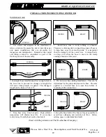
INVERTED V INSTALLATION
See “Inverted V” parts list in the back of this manual for illustrations of both typical and high yield
installations.
Connect welders ground directly to one of the items being welded anytime an arc
welder is used on the vehicle or anything connected to the vehicle. Disconnect
power cable from control box! Failure to do so can result in damage to
components on both the vehicle and/or spreader, in which case the warranty will
be null and void by manufacturer.
IMPORTANT!
Wood filler strip
installation shown.
Summary of Contents for L3020G4
Page 2: ......
Page 6: ...INSERT NEW LEADER NL WARRANTY ...
Page 7: ...TAB SAFETY ...
Page 20: ...TAB OP MAINT ...
Page 111: ...TAB G4 Spread Pattern ...

