7 - MAINTENANCE
Air cleaner - Cleaning
NOTE:
Clean the filter element after every 50 hours of service. Extremely dusty conditions may require more frequent
service intervals.
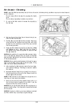
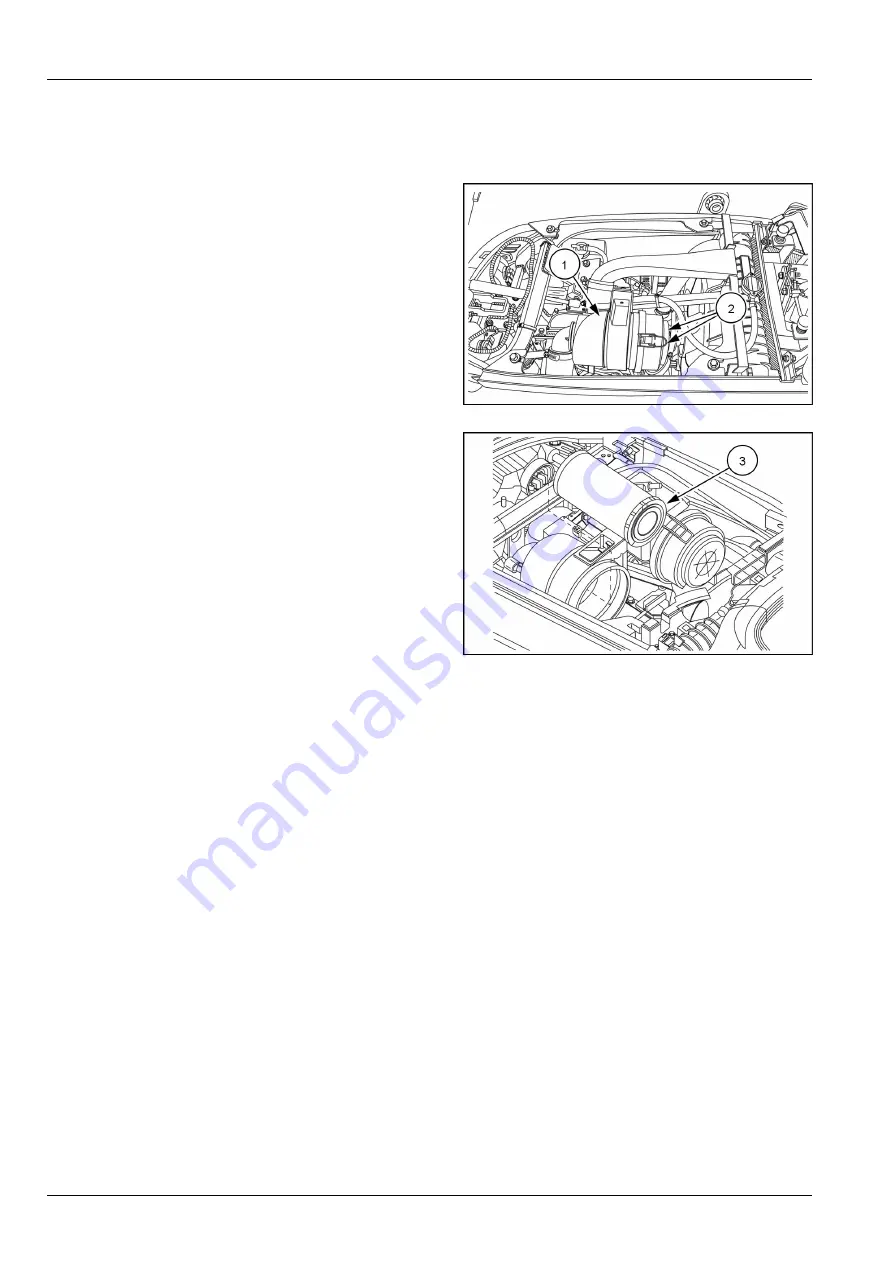
The air cleaner
(1)
is accessed by opening the tractor
hood.
The air cleaner assembly contains one element.
1. To remove the filter element, release the clips
(2)
on
the end cap.
NHIL17CT01297AA
1
2. Remove the end cap from the air cleaner body to ex-
pose the filter element
(3)
.
3. Pull the filter element
(3)
from the canister. Clean any
loose dirt from the canister and inspect the end of the
canister for dirt which may prevent the new element
from sealing properly.
4. Clean the filter element using low air pressure (
2 Kg/
cm²
(
30 psi
) or less). Blow dust from the inside to
the outside of the element (opposite to normal air flow
through element).
NOTICE:
Be careful not to rupture the filter element. Main-
tain a safe distance between the air nozzle and the filter
element when directing air up and down the clean air side
of the element pleats.
NOTICE:
Place a light inside the element to check for paper
leaks or for bonding of the paper to the end plate. If any
leaks are found, replace the element.
5. After cleaning the filter element, check the inner diam-
eter seals for damage. If damage is present, replace
the element.
6. Reinstall the filter element by inserting it into the can-
ister and pushing on the end of the element until it is
seated against the canister.
NOTE:
If filter element is not inserted far enough into can-
ister, the end cap cannot be installed.
7. Place the end cap onto the canister body, push in on
the end cap to seat it against the canister. Lock the
clips and verify the end cap is secure.
NOTICE:
Never tap the filter element with hard objects or
against a hard surface. This may dent or break the element
end cap seals.
NOTICE:
Failure to obtain a good seal between element
and the canister may cause major engine damage.
NHIL17CT01267AA
2
7-26
Summary of Contents for Workmaster 25S
Page 20: ...1 GENERAL INFORMATION 1 14 ...
Page 102: ...3 CONTROLS AND INSTRUMENTS 3 40 ...
Page 118: ...4 OPERATING INSTRUCTIONS 4 16 ...
Page 186: ...7 MAINTENANCE 7 50 ...
Page 199: ...9 SPECIFICATIONS NHIL17CT01125FA 1 NHIL17CT01124FA 2 9 9 ...
Page 200: ...9 SPECIFICATIONS 9 10 ...


