


5
Operator's Manual
5
potential conseQuence
preVention
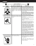
safety warnings
READ ALL SAFETY WARNINGS BEFORE USING PRESSURE WASHER
Serious injury or death may occur
from inhaling engine/burner exhaust
or dangerous vapors. The engine
exhaust from this product contains
chemicals known to the State of
California to cause cancer, birth
defects, or other reproductive
harm.
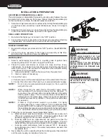
This pressure washer was designed for outdoor
use only. Never operate this pressure washer
in an enclosed area. Always make certain there
is adequate ventilation (fresh outside air) for
breathing and combustion. This will prevent
the buildup of dangerous carbon monoxide
gases. Beware of poorly ventilated areas,
or areas with exhaust fans which can cause
poor air exchange.
Follow all safety instructions provided with the
materials you are spraying. Use of a respirator
may be required when working with some
materials. Do not use this pressure washer
to dispense hazardous detergents.
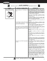
risK of inJection or
seVere cutting inJury
Serious injury or death could occur
from high pressure spray penetrating
the skin.
Keep clear of nozzle and spray! Never put
your hand, fingers or body directly over the
spray nozzle.
Never point the high pressure discharge spray
at yourself or anyone else.
Always keep operating area clear of all
persons.
DO NOT allow children to operate this unit.
SEEK EMERGENCY MEDICAL CARE if the
spray appears to have penetrated the skin!
DO NOT TREAT AS A SIMPLE CUT!!
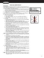
High pressure hoses and fuel lines should be
inspected daily for signs of wear. If evidence
of failure exists, promptly replace all suspect
hoses and fuel lines to prevent the possibility of
injury from the high pressure spray. If a hose
or fitting is leaking, NEVER PLACE YOUR
HAND DIRECTLY ON THE LEAK.
NEVER operate the gun with the trigger wired
in the open position. To prevent accidental
discharge, the trigger gun should be securely
locked when not in use.
Before removing the spray nozzle or servicing
the unit, ALWAYS shut off the unit and trigger
the gun to release trapped pressure. (Even
after you shut off the unit, there is high
pressure water left in the pump, hose and gun
until you release it by triggering the gun.)
risK of electrocution
or electrical sHocK
Serious injury or death may occur
from contact with electricity.
DO NOT direct spray on or into electrical
installations of any kind! This includes electrical
outlets, light bulbs, fuse boxes, transformers,
the unit itself, etc.
DO NOT allow metal components of the
pressure washer to come in contact with live
electrical components.
risK of
aspHyXiation
HaZard
Summary of Contents for MN2765HAHW
Page 1: ...operation manual MN2765HAHW MODEL NUMBER...
Page 8: ...8 8 Operator s Manual features 2500 psi HSP 2500 FEATURES 122208 CH...
Page 24: ...24 4 Copyright 2011 EX 9836 101011 FLOW CHART EMF SYSTEM HSP115 080499 BAR HSP046 072996 BAR...
Page 29: ...29 12 yright 2011 EX 9836 101011 PUMP ASSEMBLY 3 0146...
Page 31: ...31 14 EX 983 UNLOADER ASSEMBLY 8 0515...
Page 40: ...40 26 yright 2011 EX 9836 1010 WIRING SCHEMATIC WIRING DIAGRAM...