New Holland MN2765HAHW Operation Manual Download Page 16

16

18 


      Operator's Manual

storage & maintenance

specific maintenance:

ENGINE:  The engine instructions that accompany your unit detail specific  

procedures for maintenance of the engine.  Following the engine  

manufacturer’s recommendations will extend engine work life.

PUMP:  

The pump oil must be changed after the first 25 hours of operation. 

Once the initial oil change has been completed, it is recommended 

the oil be changed every 3 months or 250 hour intervals.  If oil 

appears  dirty  or  milky,  changes  may  be  required  at  a  greater 

frequency. Use the following pump oil and fill only to the center of 

the oil sight glass.  DO NOT OVERFILL!

NOZZLES:  Water flow through the spray nozzle will erode the orifice, making 

it larger, resulting in a pressure loss.  Nozzles should be replaced 

whenever pressure is less than 85% of the maximum. The frequency 

of replacement will depend upon such variables as mineral content 

in the water and number of hours the nozzle is used.  


QUICK COUPLERS:  There is an o-ring seal inside the female quick coupler.  This 

o-ring will deteriorate or, if the unit is allowed  to pump without  

the high pressure hose or nozzle attached, the o-ring may be blown 

out occasionally.  Simply insert a replacement o-ring to correct the 

leak.  (Additional o-rings can be purchased from your dealer.)

BURNER AIR ADJUSTMENT:    The  air  shutter  has  been  factory  preset  for  

proper  operation  between  sea  level  and  2000  feet  elevation  at 

standard conditions (60°F ambient water and air temperatures).  To 

assure maximum combustion efficiency at  colder temperatures and 

higher altitudes, it will be necessary to adjust the air supply to the 

combustion chamber.  A smoke spot test is recommended during 

any air shutter adjustment.  This will aid in maximizing the burner 

efficiency and avoid inefficient operation and excessive sooting of 

the combustion chamber.


1.  The machine must be running and the burner ON.


2.  Take a smoke spot test to determine if more or less air is  


required for proper combustion.


a.  If  the  test  is  greater  than  a  #3  smoke,  turn  the  shutter  


arm 

counterclockwise

  to  increase  the  air  flow  into  the 


combustion chamber.


b.  If  the  test  is  yellowish  in  color,  turn  the  shutter  arm 


clockwise

 to decrease the air flow into the combustion  


chamber.


3.  Hold onto the air shutter adjusting arm and loosen the locking  


nut.  

Move the shutter in 1/8" increments and retighten the  


locking nut after each 1/8" movement.


4.  Trigger the gun on and off slowly to make sure there is proper  


ignition. Slight or no puffing on the ignition, and a smoke spot  


test of less than #3 smoke is good.


5.  Repeat steps 2 and 3 until step 4 is attained. 

LEAKS: 

Promptly  eliminate  any  leaks  found  in  the  pumping  system  by  

removing  suspect  parts,  applying  thread  sealant  to  the  threads  

and reinstalling.  

NOTE:  If  using  teflon  tape,  be  certain  no  tape  gets  inside  any  plumbing  to 

prevent the possibility of a plugged spray nozzle. 
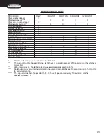
 

Model #  


      Pump Oil

   HSP   


      SAE30W non-detergent 

Summary of Contents for MN2765HAHW

Page 1: ...operation manual MN2765HAHW MODEL NUMBER...

Page 2: ...REVIEW 11 NOZZLE CONNECTION 11 WATER SUPPLY 11 UNLOADER 12 HEAT DUMP VALVE 12 PRE START INSPECTION PROCEDURES 12 operating instructions 14 15 PRIMING THE PUMP 14 START UP COLD WATER OPERATION 14 HOT W...

Page 3: ...l are as follows DANGER indicates an imminently hazardous situation which if not avoided will result in death or serious injury WARNING indicates a potentially hazardous situation which if not avoided...

Page 4: ...fuel tank Refuel with gasoline only Do not use diesel or fuel oil burner fuel tank Black When refueling the Burner Fuel Tank use No 1 or No 2 fuel oil diesel or kerosene Do not use gasoline Do not op...

Page 5: ...ighpressuredischargespray at yourself or anyone else Always keep operating area clear of all persons DO NOT allow children to operate this unit SEEK EMERGENCY MEDICAL CARE if the spray appears to have...

Page 6: ...asive surfaces such as cement Use only manufacturer recommended repair parts for your pressure washer In freezing temperatures the unit must always be warm enough to ensure there is no ice formationin...

Page 7: ...ring could occur Stay alert watch what you are doing Do not operate the unit when fatigued or under the influence of alcohol or drugs NEVER squeeze the trigger unless securely braced DO NOT overreach...

Page 8: ...8 8 Operator s Manual features 2500 psi HSP 2500 FEATURES 122208 CH...

Page 9: ...aution Risk of Fire 16 Decal Warning Caution Operating 17 Air Shutter Adjusting Arm 18 Burner On Off Switch 19 Gasoline Engine Tank 20 High Pressure Hose 21 Trigger Safety Lock 22 Trigger Gun 23 Insul...

Page 10: ...uel oil diesel or kerosene 4 Purchase gasoline fuel in quantities that may be used within 30 days Use of clean fresh lead free gasoline is recommended Leaded gasoline may be used if lead free is unava...

Page 11: ...both strainers before starting your pressure washer 4 Follow the incoming water requirements listed below a Water pressure must be a minimum of 20 pounds per square inch PSI and a maximum of 125 PSI...

Page 12: ...ck the oil level in the pump and engine 2 Inspect the water inlet strainer Clean or replace if necessary See Water Supply 2 pg 11 3 Check all hose connections to ensure they are securely tightened See...

Page 13: ...intenance instructions do not attempt to operate tHis pressure wasHer until you HaVe read and understood all safety precautions and instructions listed in tHis manual incorrect operation of tHis unit...

Page 14: ...he engine has started c Hold the trigger gun open while starting the engine according to the manufacturer s instructions in the engine manual accompanying this unit 5 Once the engine has started perfo...

Page 15: ...ergent operation NOTE This injection system is designed to apply detergents under low pressure only It will not allow detergent solutions to be introduced into the system unless the dual lance is set...

Page 16: ...preset for proper operation between sea level and 2000 feet elevation at standard conditions 60 F ambient water and air temperatures To assure maximum combustion efficiency at colder temperatures and...

Page 17: ...ater Then plug the open end of the hose with your thumb or finger Place the plugged end into the 5 gallon container of water i Start the unit Trigger the gun several times until all the air is worked...

Page 18: ...ly Water is leaking from the Heat Dump Water temperature is too high Do not allow unit to operate in Valve bypass mode with the trigger gun closed for more than 3 minutes Defective valve Replace Oil a...

Page 19: ...s to ensure there is sparking across electrodes No voltage Consult your Customer Service Pressure switch override Pressure should be over 250 PSI 18 Bar to allow burner to come on High limit switch ov...

Page 20: ...k burner air adjustment X X X X Check burner electrodes X Test water pressure X X X X Test fuel pressure X X X X Test water temperature X X X X Descale coil X Must be performed by an authorized servic...

Page 21: ...ae10W 30 engine oil capacity 20 oz pump oil grade Sae30W non detergent pump oil capacity 14 oz Fuel noZZle 1 10 60 B delaVan Btu input 185 500 hour preSSure noZZle SiZe 3 0 partS liSt For C2765HAHW ho...

Page 22: ...ions and will VOID warranty 2 NEVER make adjustments on machinery while the unit is connected to the engine without first removing the ignition cable from the spark plug Turning over the machinery by...

Page 23: ...downstream from pump Burner Fuel System Fuel Type No 1 or No 2 Fuel Oil Diesel or Kerosene Fuel Capacity gallons liters 4 15 Fuel Filter Inline Filter Fuel Pump Two Line Single Stage Fuel Pressure PSI...

Page 24: ...24 4 Copyright 2011 EX 9836 101011 FLOW CHART EMF SYSTEM HSP115 080499 BAR HSP046 072996 BAR...

Page 25: ...on when the trigger gun is closed the SAFETY RELIEF 12 will relieve and allow water to exit safely The heated water then flows through the HIGH PRESSURE HOSE 13 and to the TRIGGER GUN ASSEMBLY 14 whi...

Page 26: ...1 3 Decal Warning Hot Coil Exhaust E S See 34 9001 N A Sep 1 4 Decal Allow to Cool E S See 34 9001 N A Sep 1 5 Decal Hot Surface E S See 34 9001 N A Sep 1 6 Decal Risk of Fire E S See 34 9001 N A Sep...

Page 27: ...2 33 Elbow 23 0034 1 10 Grommet 33 0366 1 34 Switch 32 0798 1 11 Washer 28 0057 1 35 Coil Outlet Block 24 0138 1 12 Brake Handle Assembly 20 0552A01 1 36 Pressure Relief Valve 22 0272 1 13 Screw 27 0...

Page 28: ...ressure Hose 15 0090 1 4 Garden Hose Swivel 23 0095 1 17 Elbow 24 0004 1 5 Pump 3 0146 1 18 Pressure Switch 22 0243 1 6 Thermo Valve 22 0005 1 19 Bolt 27 0118 4 7 Pump Adapter 38 0054 1 20 Lockwasher...

Page 29: ...29 12 yright 2011 EX 9836 101011 PUMP ASSEMBLY 3 0146...

Page 30: ...ckwasher 29 0153 8 12 O ring 25 0370 1 38 Bolt 27 8875 8 13 Oil Sight Glass 46 0670 1 39 Manifold 46 0730 1 14 Reflector 46 0824 1 40 O ring 25 0372 1 15 Retainer 46 0671 1 41 Plug 39 0088 1 16 O ring...

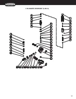
Page 31: ...31 14 EX 983 UNLOADER ASSEMBLY 8 0515...

Page 32: ...See 70 0338 N A Sep 1 11 O ring See 70 0292 70 0366 N A Sep 1 34 Chemical Injector Body See 70 0338 N A Sep 1 12 Piston Guide 8 0502 1 35 Spring 8 0520 1 13 O ring 25 0403 2 36 Ball 8 0521 1 14 O ring...

Page 33: ...rew N A 4 3 Cover N A 1 4 O ring See 70 0306 N A Sep 1 5 Micro Switch N A 1 6 Retainer Clip N A 1 7 Body N A 1 8 O ring See 70 0306 N A Sep 2 9 Back up Ring See 70 0306 N A Sep 1 10 Piston N A 1 11 Wa...

Page 34: ...g 32 0465 3 7 Flatwasher 28 0022 5 25 Elbow 23 0287 1 8 Tensioner Base 10 0071 1 26 Solenoid 44 0098 1 9 Tensioner Sheave Shaft Assembly Inc 6 10 11 850 0166 1 27 Elbow 23 0249 1 10 Shaft 33 0212 1 28...

Page 35: ...Nozzle Holder 33 0182 1 6 Air Diverter Stem Assembly 20 0377A01 1 22 Electrode 32 0377 2 7 Lockwasher 28 1009 1 23 Washer 28 1007 2 8 Nut 30 6001 1 24 Electrode Mounting Plate 33 0180 1 9 Insulation...

Page 36: ...es 7 850 0214 121797 BAR FUEL TANK 850 0214 22 EX 9836 101011 850 0214 34 9001 121797 BAR FUEL TANK 850 0214 REF DESCRIPTION PART QTY 1 Fuel Tank Assembly Inc 2 8 850 0214 1 2 Plug 23 0296 1 3 Fuel Ta...

Page 37: ...Plug 7 Body 8 Plug FUEL PUMP 3 0020 OMHSP018 040694 BAR 23 EX 9836 101011 HSP018 3 0020 041597 BAR FUEL PUMP 3 0020 REF DESCRIPTION PART QTY 1 Fuel Pump Complete Right Hand 3 0020 1 2 Cover Screw 46...

Page 38: ...r Cord FUEL SOLENOID 44 0098 OMHSP013 121698 BAR 24 EX 9836 101011 HSP013 44 0098 121698 BAR FUEL SOLENOID 44 0098 REF DESCRIPTION PART QTY 1 Solenoid Complete 12V 44 0098 1 2 Solenoid Body 46 1013 1...

Page 39: ...9836 101011 HSP121 052908 CH EMF SYSTEM 850 0271 REF DESCRIPTION PART QTY 1 EMF Assembly Includes 2 17 850 0271 1 2 Blower Flange Assembly Includes 3 6 850 0162 1 3 Bearing 48 0041 2 4 Flange Blower 3...

Page 40: ...40 26 yright 2011 EX 9836 1010 WIRING SCHEMATIC WIRING DIAGRAM...

Reviews: