


22
2
©
Copyright 2011
EX-9836-101011
This Parts Listing has been compiled for your benefit. You can be assured your hot water pressure washer was constructed and designed with quality and
performance in mind. Each component has been rigorously tested to insure the highest level of quality.
The contents of this Parts Listing are based on the latest product information available at the time of publication. Manufacturer reserves the right to make changes
in price, color, materials, equipment, specifications or models at any time without notice.
WARNING
THIS IS A PROFESSIONAL HIGH PRESSURE, HOT WATER PRESSURE WASHER. CAUTION SHOULD BE OBSERVED WHEN USING OR REPAIRING
THIS UNIT! READ AND FOLLOW THE SAFETY WARNINGS LISTED BELOW BEFORE ATTEMPTING ANY REPAIRS ON THIS PRESSURE WASHER!
SAFETY WARNINGS
1. NEVER alter or modify the equipment. Be sure any accessory items and system components being used will withstand the pressure developed. Use only
genuine manufacturer parts for repair of your pressure washer. Failure to do so can cause hazardous operating conditions and will VOID warranty.
2. NEVER make adjustments on machinery while the unit is connected to the engine without first removing the ignition cable from the spark plug. Turning over
the machinery by hand during adjustment or cleaning might start the engine and machinery with it, causing serious injury to the operator.
3. Know how to stop and bleed pressures quickly. Be thoroughly familiar with controls.
4. Before servicing the unit, turn unit off, relieve the water pressure and allow the unit to cool down. Do not make repairs while the unit is running. Service in a
clean, dry, flat area. Block the wheels to prevent the unit from moving. Be especially careful to properly dispose of any flammable materials.
5. After testing the machine, DO NOT leave the pressurized unit unattended. Shut off the unit and release trapped pressure before leaving.
Table of Contents
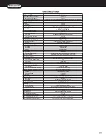
SPECIFICATIONS ...................................................................................................................................................................................................................................3
FLOW CHART ........................................................................................................................................................................................................................................4
EMF SYSTEM .........................................................................................................................................................................................................................................4
GENERAL THEORY OF OPERATION ...................................................................................................................................................................................................5
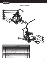
DECAL PLACEMENT .............................................................................................................................................................................................................................6
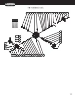
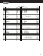
FRAME ASSEMBLY ...............................................................................................................................................................................................................................8
ENGINE/PUMP ASSEMBLY .................................................................................................................................................................................................................10
PUMP ASSEMBLY (3-0146) .................................................................................................................................................................................................................12
UNLOADER ASSEMBLY (8-0515) .......................................................................................................................................................................................................14
PRESSURE SWITCH (22-0243) ...........................................................................................................................................................................................................16
HEAT EXCHANGER/EMF SYSTEM .....................................................................................................................................................................................................18
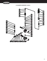
BOILER ASSEMBLY (850-0399) ..........................................................................................................................................................................................................20
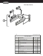
FUEL TANK (850-0214) ........................................................................................................................................................................................................................22
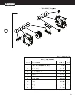
FUEL PUMP (3-0020) ...........................................................................................................................................................................................................................23
FUEL SOLENOID (44-0098) .................................................................................................................................................................................................................24
EMF SYSTEM (850-0271).....................................................................................................................................................................................................................25
WIRING SCHEMATIC ...........................................................................................................................................................................................................................26
WIRING DIAGRAM ...............................................................................................................................................................................................................................27
Summary of Contents for MN2765HAHW
Page 1: ...operation manual MN2765HAHW MODEL NUMBER...
Page 8: ...8 8 Operator s Manual features 2500 psi HSP 2500 FEATURES 122208 CH...
Page 24: ...24 4 Copyright 2011 EX 9836 101011 FLOW CHART EMF SYSTEM HSP115 080499 BAR HSP046 072996 BAR...
Page 29: ...29 12 yright 2011 EX 9836 101011 PUMP ASSEMBLY 3 0146...
Page 31: ...31 14 EX 983 UNLOADER ASSEMBLY 8 0515...
Page 40: ...40 26 yright 2011 EX 9836 1010 WIRING SCHEMATIC WIRING DIAGRAM...