


19
Operator's Manual
21
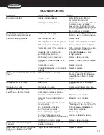
troublesHooting
SYMPTOM
PROBABLE CAUSE
REMEDY
Water is leaking under heat
Safety relief device is relieving
1. Detect and correct unloader or
exchanger coil.
caused by an unloader or pressure
pressure switch problem.
switch problem.
2. Replace safety relief device.
NEVER run unit without safety relief
device. Doing so can cause an
explosion!
Burner will not ignite.
Burner switch is not turned on.
Check switch position.
Out of fuel.
Refuel.
Trigger gun is closed.
Open trigger gun for pressure.
EMF Drive belt loose or broken.
Adjust or replace as necessary.
Flexible coupler broken.
Replace.
Dirty or clogged fuel filter.
Replace.
Fuel pump sucking air.
Tighten all fuel intake connections.
Eliminate leaks in intake line.
Fuel pump inoperative.
Check pressure, replace if needed.
Dirty or clogged fuel nozzle.
Replace fuel nozzle.
Ignition module.
Consult your Customer Service.
Ignition electrodes damaged or worn. With unit running and trigger gun
closed, look through burner sight
glass to ensure there is sparking
across electrodes.
No voltage.
Consult your Customer Service.
Pressure switch override.
Pressure should be over 250 PSI/
18 Bar to allow burner to come on.
High limit switch override.
Allow unit to cool down before
reigniting.
Improper burner air adjustment.
Adjust as shown on page 16.
Fuel solenoid valve failure.
Replace.
Burner runs erratically.
Water in the fuel oil.
Drain fuel tank and replace with
clean fuel.
Dirty fuel filter.
Replace.
Dirty fuel nozzle.
Replace.
Improper air adjustment setting.
Adjust as shown on page 16.
Fuel pump malfunctioning.
Replace.
Burner runs, but will not heat.
Poor or improper fuel supply.
Check fuel to ensure it is correct.
Drain tank and filter if necessary
and refill with proper fuel.
Low fuel pump pressure.
Check fuel pump pressure, replace
if needed.
Dirty fuel nozzle.
Replace.
Improper air adjustment setting.
Adjust as shown on page 16.
Scale build up in heat exchanger coil. Consult your Customer Service.
Burner discharges white smoke.
Low on fuel.
Refuel. If white smoke persists,
consult your Customer Service.
Excessive air supply.
Adjust as shown on page 16.
Burner discharges black smoke.
Insufficient air supply.
Adjust as shown on page 16.
Summary of Contents for MN2765HAHW
Page 1: ...operation manual MN2765HAHW MODEL NUMBER...
Page 8: ...8 8 Operator s Manual features 2500 psi HSP 2500 FEATURES 122208 CH...
Page 24: ...24 4 Copyright 2011 EX 9836 101011 FLOW CHART EMF SYSTEM HSP115 080499 BAR HSP046 072996 BAR...
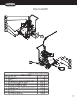
Page 29: ...29 12 yright 2011 EX 9836 101011 PUMP ASSEMBLY 3 0146...
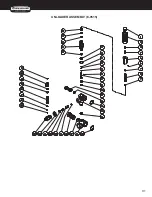
Page 31: ...31 14 EX 983 UNLOADER ASSEMBLY 8 0515...
Page 40: ...40 26 yright 2011 EX 9836 1010 WIRING SCHEMATIC WIRING DIAGRAM...