-40-
10. Troubleshooting
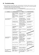
Before requesting for repair, please refer to the table below. If the detector does not return to normal
operation after performing the corresponding steps in the table, or if your issue is not found in the table,
consult New Cosmos or its authorized representative.
In the event of a device failure, refer to 7-
3. ―Trouble Alarm Operation.‖
In the case of a communication problem, refer to a separate PS-7 communication specifications guide.
Troubleshooting
Problem
Probable cause
Steps
Reference section
Green POWER LED
does not turn on
Base unit’s power
switch is in the OFF
position
Set the switch to the
ON position.
7-1.Operation
Procedure
Main unit’s power
switch is in the OFF
position
Set the switch to the
ON position.
7-1.Operation
Procedure
Incorrect wiring
Check and rewire.
Securely connect the
wires to the terminals.
6-3. Wiring
Procedure
Connector to the
front panel is loose
Check and rewire.
Securely connect the
wires to the terminals.
9-3. Sampling Unit
Replacement
Blown fuse
Replace the fuse.
*Turn off the detector
before replacement.
5-3. Base Unit
Amber TROUBLE
LED flashes
Low flow rate due to
clogged filter
element
Replace the filter
element.
9-1. Filter Element
Replacement
Low flow rate due to
pump failure
Replace the sampling
unit.
9-3. Sampling Unit
Replacement
Low flow rate due to
clogged tubing
Remove clog from the
tubing.
Connector to the
pump unit is loose
Check and rewire.
Securely connect the
wires to the terminals.
9-3. Sampling Unit
Replacement
Incorrect sensor
installed (data does
not match the last
installed sensor
type)
Install the correct
sensor type.
To install a different
sensor type, press
COMM. button to
renew the data.
7-1.Operation
Procedure
Sensor unit failure
Replace the sensor
unit.
9-2. Sensor Unit
Installation/Replacem
ent
Absent sensor unit
Install the sensor unit.
9-2. Sensor Unit
Installation/Replacem
ent
Flow sensor output
is unstable
immediately after
powering up
Leave the detector on
for about 30 minutes.
Gas concentration
value and
―_ _ _ _‖
flashing alternately
MNT switch is set to
MNT1 or MNT2
Set the MNT switch to
the center position for
normal operation
7-5. Maintenance
Mode


