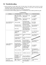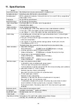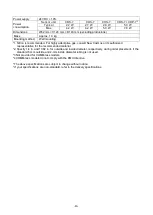
-29-
7-5. Maintenance Mode
Setting
The MNT switch has three modes
— maintenance mode 1 (MNT1), maintenance mode 2 (MNT2), and
normal operation mode (gas-monitoring mode).
Set the MNT switch to MNT1 or MNT2 on
the base unit’s front, accordingly ―MNT1‖ or ―MNT2‖ will be shown
on the LCD. To return to the normal operation mode, set the MNT switch to the center position.
Operation
During MNT1, gas alarm contacts and trouble alarm open collector are disabled.
During MNT2, gas alarm contacts and trouble alarm open collector are disabled, and the analog output is
fixed at 4.0 mA (or 17.4 mA for oxygen).
In either maintenance mode, the amber TROUBLE LED flashes, and the detected gas concentration is shown
on the LCD.
Gas alarm
contact
Trouble
alarm open
collector
Analog output
Amber
TROUBLE
LED
On display
MNT1
(host maintenance mode)
Disabled
(fixed at
OFF)
Disabled
(fixed at ON)
Value
corresponding to
the detected gas
concentration.
Flashes
Detected gas
concentration
value
MNT2
Disabled
(fixed at
OFF)
Disabled
*1
(fixed at ON)
Fixed at 4.0 mA or
17.4 mA
Flashes
Detected gas
concentration
value
WARNING
During normal operation (gas-monitoring mode), ensure the MNT switch is set to the center
position. Gas alarm contacts and trouble alarm open collector do not activate during MNT1/MNT2.
When the MNT switch is set to MNT2, the analog output is fixed at 4.0 mA or 17.4 mA.
MNT switch
MNT1
– normal operation – MNT2
(center)
Lift the cover flap open
CAUTION
*1. Trouble alarm will activate if the main unit
’s power switch is set to the OFF position while in the
MNT1 or MNT2 mode (OFF).
*2. The analog output may change when the main unit
’s power switch is set to the OFF position.
MNT1 or MNT2 modes are enabled with the base unit and without the main unit. The base
unit can produce a 4.0 mA or 17.4 mA analog output while in the MNT2 mode. This function
is useful for loop check at startup, etc.
For COMM-less models, a 4.0 mA or 17.4 mA analog output can be produced only when a
loop checker (LC-7) is attached.
NOTE


