11
ArchiTech Cylindrical Lock & Surface-Mounted Networx Control Unit Mounting and Installation Instructions
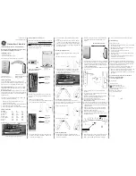
12. USING THE CYLINDRICAL DRILL JIG
The
optional
Cylindrical Drill Jig
(part #N90S1DJ)
is used with solid wood doors only
. For hollow metal doors, jump to
step 12E. If you want to use the
Wiring Plate
(HW1945) in place of the
Cylindrical Drill Jig
, jump back to step 11.
PURPOSE OF THE JIG
The
Jig
is used to drill a diagonal 1/2" hole through a solid
wood door, to provide path for the
Cylindrical Lock Motor Wire
,
allowing this wire to run to the 5/8" diameter thru-hole and be
connected to the
Surface-Mounted Networx Control Unit
.
The
Jig
will be clamped to the
inside door surface
, and the
hole will be drilled starting from the 5/8" diameter thru-hole and
ending at the 2-1/8" diameter door chassis hole.
Fig. 12 displays two "side views" to show how this
Cylindrical
Drill Jig
is inserted in the door, and the path of this drilled
interior hole.
Before you can drill, an "
Alignment Puck
" must be fastened to
the
Cylindrical Drill Jig
.
PURPOSE OF THE "ALIGNMENT PUCK"
When
the
Cylindrical Lock Body
is correctly inserted into the
door (see Fig 12A), the
Cylindrical Lock Motor Wire
is always
located on the side of the
Cylindrical Lock
Body
that is
fur-
thest from the latch
. Therefore, this
Alignment Puck
is de-
signed to shift the
Jig
to align with the location of the
Cylindrical
Lock Motor Wire
. In addition, the
Jig
is also positioned to
avoid the 3/8" (5/16") thru-hole (see Fig 12A).
12A. SELECT PROPER POSITION OF THE "ALIGNMENT PUCK"
As shown in Fig. 12AA, the rear of the
Cylindrical Drill Jig
in-
cludes an adjustable "
Alignment Puck
" that must be fastened to
one of the two screw holes at the bottom of the
Jig
with a Phil-
lips head screw (provided). To ensure the hole to be drilled
aligns with the location of the
Cylindrical Lock Motor Wire
, pro-
ceed as follows:
From the "inside" ("protected" side) of the door:
If the latch is
on the left side, select Hole A; if the latch is on the right side,
select Hole B.
Example:
The photograph shown in Fig 12A was taken
from the inside of the door; with the latch located on the left
side, use Hole A to shift the
Jig
away from the latch, to align
with the
Motor Wire
.
FIG. 12: JIG IS INSERTED INTO THE INSIDE
("PROTECTED") SIDE OF THE DOOR.
VIEW AT RIGHT SHOWS HOLE PATH
(5/8"
THRU-
HOLE)
JIG
(SIDE VIEW)
(SIDE VIEW)
(DOOR E
D
GE
)
(DOOR E
D
GE
)
(INSI
D
E D
OOR
SURFAC
E)
(OUTSI
DE D
O
O
R
SURFA
C
E)
(OUTSI
DE D
O
O
R
SURFA
C
E)
AL
IGNME
N
T
PUCK
FIG. 12A: MOTOR WIRE IS ALWAYS
LOCATED FURTHEST FROM LATCH
Latch
Motor Wire
3/8" (5/16")
thru-hole
FIG. 12AA: CYLINDRICAL DRILL JIG
"
Alignment
Puck
"
Hole
A
Hole
B


