


GYDA-SC
Rev.
4
7.2
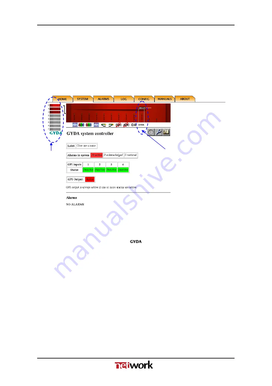
GYDA web interface – screen navigation
The web interface with the information view of the GYDA System Controller is
shown in figure 11. To the left we see the detection and indication of the 1-8
frames that are connected to the system. In this case frame 0 is selected of the
3 frames that are connected to GYDA. On the frame itself, we see the
indication of the active card as a grey frame on the red front. By clicking the
different positions or icons of the frame, the different card modules can be
controlled.
Frame
inicator
Card indicator
Figure 11: Information view of the GYDA System Controller.
Figure 12: The icon for the GYDA System Controller.
As shown in figure 11, we can get a summary of the alarms in the system.
Each alarm can be in one of three different states:
-
Active
(Red colour). An alarm is present in the system, and is not
acknowledged.
-
Acknowledged
(Yellow colour). A present alarm that has been
acknowledged.
The alarm will disappear from the list as soon as the condition that set the
alarm no longer exists.
-
Restored
(Green colour). The condition that set the alarm does no longer
exist. The alarm must be acknowledged in order to disappear from the list.
The status for the GPI inputs of the GYDA System Controller is shown below
the alarm list. The status can be either
active
(triggered by an external device)
or
inactive
.
16


