NTI XTENDEX KVM EXTENDER
3
INSTALLATION
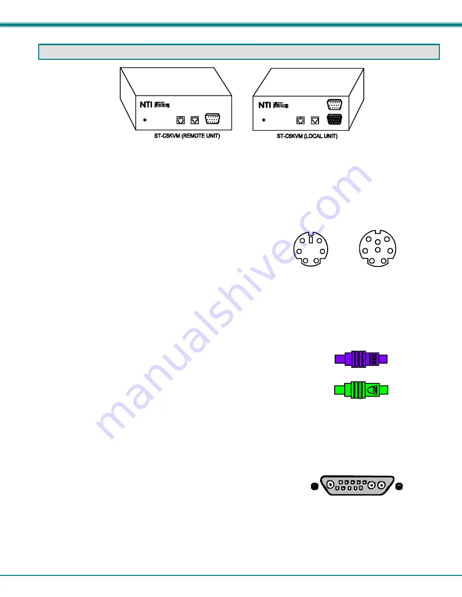
The Local Unit
1. Position the Local Unit where the AC adapter, the CAT5 cable, the video cable, and the mouse/keyboard cable from
the CPU (or other device into which it will be plugged) can reach it.
2. Two different Keyboard/Mouse cables have been provided, for the two possible plug configurations compatible with
the NTI ST-C5KVM CAT5 Extender, depending on what style of computer the Extender is being connected to;
VKTINT-3-MM for a PC or SKTINT-3-MM for a SUN.
Identify which cable is correct for your installation and proceed to step 3.
NOTE: If the extender is being installed with a PC style computer, the Keyboard/Mouse cable will have one connector on
one end for attachment to the Local Unit, and two connectors on the other end for connection to the Mouse and
Keyboard ports on the CPU separately (VKTINT-3-MM). If the Extender is being installed with a SUN style
computer, which does not have a separate Mouse port on the CPU, then only one connector will be at each end
of the appropriate cable (SKTINT-3-MM). So if a SUN style computer is being extended, skip step 5 below.
3. Connect one end of the mouse/keyboard cable (VKTINT-3-MM or SKTINT-3-MM) to the KB/Mouse port on the back
of the Local Unit.
4. Connect the end of the KB/Mouse cable with the keyboard symbol
on it to the keyboard port on the back of the CPU.
5. Connect the end of the KB/Mouse cable with the mouse symbol
on it to the mouse port on the back of the CPU.
6. Connect one end of the video cable to the VIDEO port on the back of the Local
Unit.
7. Connect the other end of the video cable to the VGA port on the back of the CPU.
If a SUN CPU is being connected, depending upon the video connector of the SUN CPU, it may be necessary to attach an
NTI #13W3M-15HDF (SUN video port-to-VGA adapter) to the video port on the CPU first, and then connect the video cable to the
adapter.
8. If a local monitor will be used, connect it to the 15HD female MONITOR port on the back of the Local Unit.
9. Connect the CAT5 cable to the “CAT5” port on the back of the Local Unit. (If an RJ45 wall outlet is being used,
connect the other end of the extension cable to it.) When properly inserted the cable end should snap into place.
PC
1
2
4
3
6
5
SUN
1
2
4
3
6
5
Sun 13W3 Video Connector
1275 DANNER DR., AURORA OH. 4420 2
TEL. 330-56 2-7070 www .nti1.com
CAT5
Video
CAT5
Video
1275 DANNER DR., AURORA OH. 4420 2
TEL. 330-56 2-7070 www .nti1.com
5VDC
(Rear View)
(Rear View)
5VDC
Monitor
1
2
4
3
6
5
1
2
4
3
6
5
KB/Mouse
KB/Mouse
(Mouse)
(Keyboard)


