NETGEAR ProSafe FS750T2 User Manual Download Page 19

Page 19 of 21 

APPENDIX B: TROUBLESHOOTING 

This chapter provides information about troubleshooting the NETGEAR ProSafe FS750T2 Smart Switch. Topics include: 

o

 Troubleshooting 

chart 

o

 Additional 

troubleshooting suggestions 


Troubleshooting Chart 

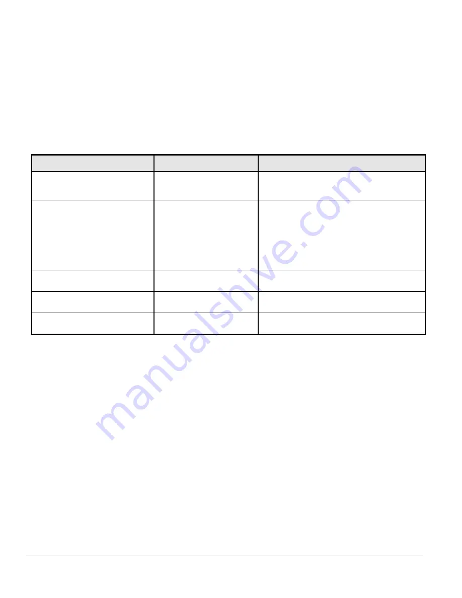
Table B-1 lists symptoms, causes, and solutions of possible problems.


Table B-1. Troubleshooting Chart


Symptom


Cause


Solution


Power

 LED is off 

No power is received 

Check the power cord connections for the switch at the 
switch and the connected device 
Make sure all cables used are correct and comply with 
Ethernet specifications 

Link/ACT

 LED is off 

Port connection is not working 

Check the crimp on the connectors and make sure that the 
plug is properly inserted and locked into the port at both the 
switch and the connecting device 
 
Make sure all cables used are correct and comply with 
Ethernet specifications. See Appendix D 
 
Check for a defective adapter card, cable, or port by testing 
them in an alternate environment where all products are 
functioning 

File transfer is slow or performance 
degradation is a problem 

Half- or full-duplex setting on the 
switch and the connected device 
are not the same 

Make sure the attached device is set to auto negotiate 

A segment or device is not recognized as 
part of the network 

One or more devices are not 
properly connected, or cabling does 
not meet Ethernet guidelines 

Verify that the cabling is correct. Be sure all connectors are 
securely positioned in the required ports. Equipment may 
have been accidentally disconnected 

Link/ACT

 LED is flashing continuously on 

all connected ports and the network is 
disabled 

A network loop (redundant path) 
has been created 

Break the loop by ensuring that there is only one path from 
any networked device to any other networked device 


Additional Troubleshooting Suggestions 

If the suggestions in Table B-1 do not resolve your problem, refer to the troubleshooting suggestions in this section.


Network Adapter Cards 

Make sure the network adapter cards installed in the PCs are in working condition and the software driver has been installed. 
 

Configuration 

If problems occur after altering the network configuration, restore the original connections and determine the problem by implementing the new 
changes, one step at a time. Make sure that cable distances, repeater limits, and other physical aspects of the installation do not exceed the 
Ethernet limitations. 
 

Switch Integrity 

If required, verify the integrity of the switch by resetting the switch. To reset the switch, use the Tools> Reset command or remove AC power from 
the switch and then reapply AC power. If the problem continues, contact NETGEAR technical support. In North America, call 1-888-NETGEAR. If 
you are outside of North America, please refer to the support information card included with your product. 
 

Auto Negotiation 

The 10/100/1000 Mbps ports negotiate the correct duplex mode and speed if the device at the other end of the link supports auto negotiation. If the 
device does not support auto negotiation, the switch only determines the speed correctly and the duplex mode defaults to half-duplex. 
The gigabit port on the Gigabit module negotiates speed, duplex mode, and flow control, provided that the attached device supports auto-
negotiation. 


Symptom Cause Solution 

Summary of Contents for ProSafe FS750T2

Page 1: ...tice This device complies with part 15 of the FCC Rules Operation is subject to the following two conditions This device may not cause harmful interference This device must accept any interference rec...

Page 2: ...le brouillage radio lectrique du minist re des Communications du Canada Customer Support For assistance with installing and configuring your NETGEAR system or with questions or problems following inst...

Page 3: ...ching 12 Backbone Switching 13 CHAPTER 4 INSTALLATION 14 Step 1 Preparing the Site 14 Step 2 Installing the Switch 14 Step 3 Checking the Installation 15 Step 4 Connecting Devices to the Switch 15 Ste...

Page 4: ...FIGURE 2 3 RESET BUTTON OF THE FS750T2 SMART SWITCH 10 FIGURE 2 4 FACTORY DEFAULTS BUTTON OF THE FS750T2 SMART SWITCH 11 FIGURE 3 1 EXAMPLE OF DESKTOP SWITCHING 12 FIGURE 3 2 EXAMPLE OF BACKBONE SWITC...

Page 5: ...Page5of21 Tables TABLE 2 1 FRONT PANEL LEDS 10 TABLE 4 1 SITE REQUIREMENTS 14 TABLE B 1 TROUBLESHOOTING CHART 19...

Page 6: ...f administrative management with a package of features for the observation configuration and control of your network With a Web based Graphical User Interface GUI the switch s many capabilities can be...

Page 7: ...Protocol Q2 2005 RFC 1157 SNMP v1 Q2 2005 Full compatibility with IEEE standards o IEEE 802 3i 10BASE T o IEEE 802 3u 100BASE TX o IEEE 802 3z ab 1000BASE X 1000Base T o IEEE 802 3x full duplex flow c...

Page 8: ...fe 48 port 10 100 Smart Switch with 2 Gigabit ports FS750T2 Rubber footpads for tabletop installation Power cord Rack mount kit for installing the switch in a 19 inch rack Installation guide Smart Swi...

Page 9: ...RJ 45 port the switch automatically ascertains the maximum speed 10 or 100 or 1000 Mbps and duplex mode half or full duplex of the attached device All ports support unshielded twisted pair UTP cable...

Page 10: ...on Power Green On Off Power is supplied to the switch Power is disconnected Green On or Blinking 100 Mbps Link or Activity 10 100 Mbps LED Yellow On or Blinking 10 Mbps Link or Activity On Link 1000 M...

Page 11: ...Default Button to enable you to clear out the current configuration and return to the factory settings This will clear out all settings including the password VLAN settings and port configurations Fi...

Page 12: ...ches This chapter shows how the switch can be used in various network environments Topics include Desktop switching Backbone switching Desktop Switching Your NETGEAR ProSafe FS750T2 Smart Switch can b...

Page 13: ...our NETGEAR ProSafe FS750T2 Smart Switch can be used with a backbone switch to build a small network that enables users to have lightening fast access to servers and the rest of the network Figure 3 2...

Page 14: ...exhausts hot air vents and heaters Operating humidity The installation location should have a maximum relative humidity of 90 non condensing Ventilation Do not restrict airflow by covering or obstruc...

Page 15: ...ting Devices to the Switch Connect each device to an RJ 45 network port on the switch s front panel see Figure 4 4 Use Category 5 Cat5 unshielded twisted pair UTP cable terminated with an RJ 45 connec...

Page 16: ...not go on check that the power cable is plugged in correctly and that the power source is good If this does not resolve the problem refer to Appendix B Troubleshooting Step 7 Switch Management throug...

Page 17: ...hnique for identifying and alerting administrators about connections such as those associated with switch ports that are experiencing congestion or failure or exceeding an administrator defined thresh...

Page 18: ...a network and logically blocks the redundant paths ensuring that only one route exists between any two LANs Spanning Tree Protocol STP A protocol that finds the most efficient path between segments o...

Page 19: ...lashing continuously on all connected ports and the network is disabled A network loop redundant path has been created Break the loop by ensuring that there is only one path from any networked device...

Page 20: ...Per port SFP port Link Activity Per device Power Performance Specifications Forwarding modes Store and forward Bandwidth 13 6 Gbps Network latency Less than 20 microseconds for 64 byte frames in stor...

Page 21: ...Page21of21 Modules AGM731F 1000BASE SX SFP GBIC for multimode fiber AGM732F 1000BASE LX SFP GBIC for single mode fiber...

Reviews: