


Page 16 of 21
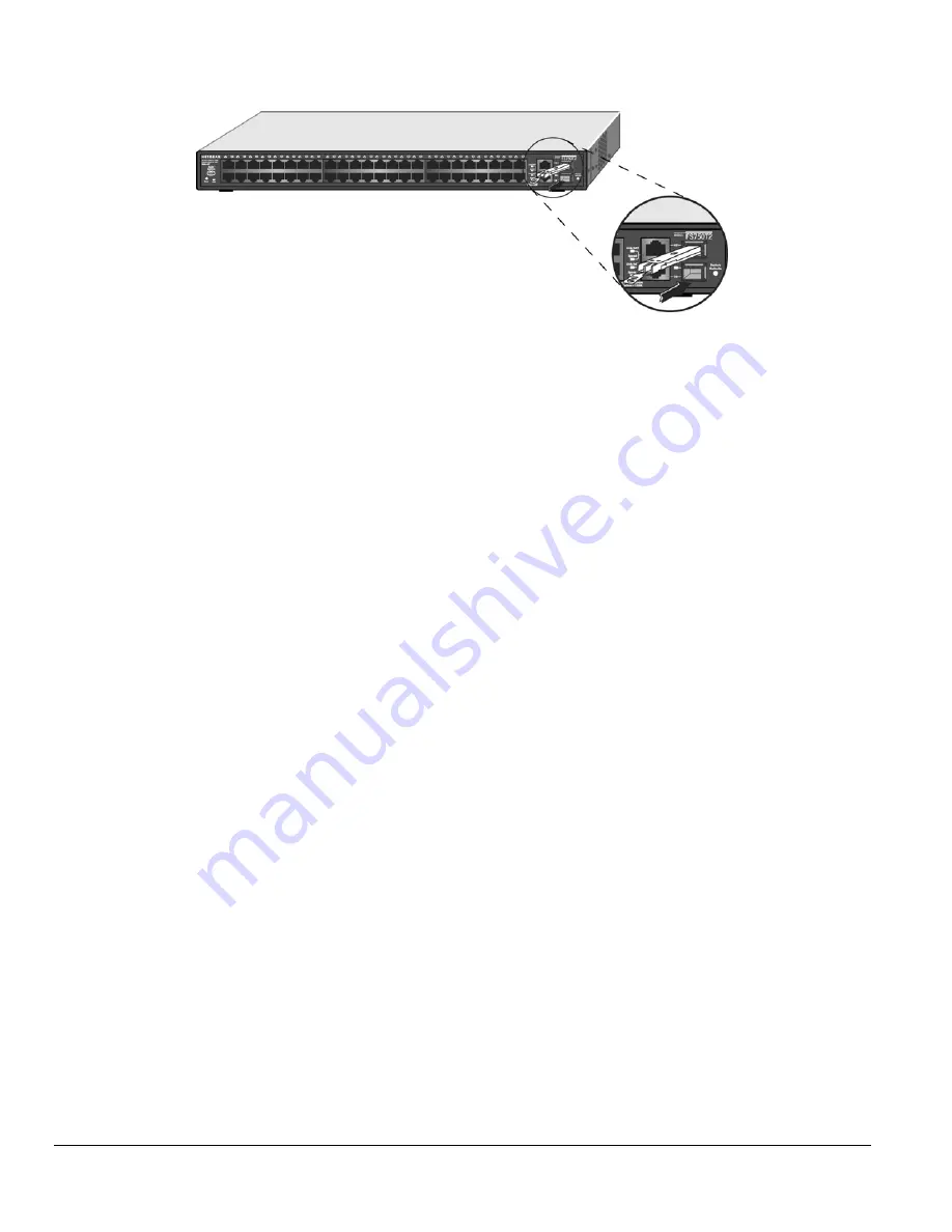
Figure 4-3. Installing a SFP GBIC Module into FS750T2
Step 6: Applying AC Power
NETGEAR ProSafe FS750T2 Smart Switch does not have an ON/OFF switch; the only method of applying or removing AC power is by connecting
or disconnecting the power cord. Before you connect the power cord, select an AC outlet that is not controlled by a wall switch, which can turn off
power to the switch. After you select an appropriate outlet, use the following procedure to apply AC power.
Connect the female end of the supplied AC power adapter cable to the power receptacle on the back of the switch.
Connect the 3-pronged end of the AC power adapter cable to a grounded 3-pronged AC outlet.
When you apply power, the
PWR
LED on the switch’s front panel will be Green.
If the
PWR
LED does not go on, check that the power cable is plugged in correctly and that the power source is good. If this does not resolve the
problem, refer to Appendix B, Troubleshooting.
Step 7: Switch Management through a Web Browser or Utility Program (Initial Configuration)
Your NETGEAR ProSafe FS750T2 Smart Switch contains software for viewing, changing, and monitoring the way it works. This management
software is not required for the switch to work. You can use the built-in RJ-45 Gigabit ports without using the management software. However, the
management software can let you setup VLAN and Trunking features and also improve the efficiency of the switch and, as a result, improve its
overall performance as well as the performance of your network.
After you power-up the switch for the first time, you can configure it using a Web browser or a utility program called Smartwizard Discovery. For
more information about managing the switch, see the
User Manual
on the
Smart Switch Resource CD
.


