


Page 15 of 21
Figure 4-1. Attaching Mounting Brackets
Step 3: Checking the Installation
Before you apply power:
o
Inspect the equipment thoroughly.
o
Verify that all cables are installed correctly.
o
Check cable routing to make sure cables are not damaged or creating a safety hazard.
o
Be sure all equipment is mounted properly and securely.
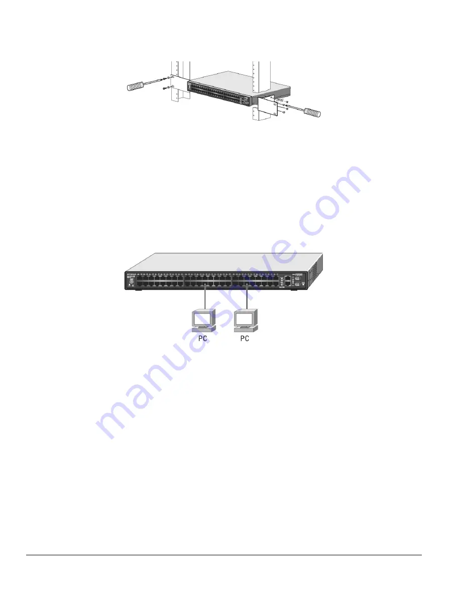
Step 4: Connecting Devices to the Switch
The following procedure describes how to connect devices to the switch’s RJ-45 ports. Your NETGEAR ProSafe FS750T2 Smart Switch contains
Auto Uplink™ technology, which allows you to attach devices using either straight-through or crossover cables.
Figure 4-2. Connecting Devices to the Switch
Connect each device to an RJ-45 network port on the switch’s front panel (see Figure 4-4). Use Category 5 (Cat5) unshielded twisted-pair (UTP)
cable terminated with an RJ-45 connector to make these connections.
Note
: Ethernet specifications limit the cable length between the switch and the attached device to 100 m (328 ft).
Step 5: Installing a SFP GBIC Module
The following procedure describes how to install a SFP GBIC module in the switch’s SFP GBIC module bays. Standard SFP GBIC Modules are
sold separately from the FS750T2. If you do not want to install a SFP GBIC module at this time, skip this procedure.
To install a SFP GBIC module:
z
Insert the SFP module into the SFP GBIC module bay. Press firmly to ensure the module seats into the connector.
To install additional Gigabit Ethernet modules, repeat this procedure


