background image

44 | 

P a g e


Ness IQ-SDI Users Manual 

 Click (

 ) each frame on Resolution column to select recording resolution of a corresponding camera. User may select one 

of 360x 240(288), 720x240(288), 720x480(576), 1280x720 and 1920x1080 

 Click (

 ) each frame on Frames column to select recording rate of a corresponding camera. Recording rate varies by 

camera. Below lists the maximum recording rate of each camera. 


Ness IQ-SDI Model


360x 240(288) 

720x240(288) 

720x480(576) 

1280 x 720 

1920 x 1080 

4 Channel DVR 

Max. 25 fps per Channel 

Max. 25 fps per Channel 

Max. 25 fps per Channel 

Max. 12 fps per Channel 

Max. 7 fps per Channel 

8 Channel DVR 

Max. 25 fps per Channel 

Max. 25 fps per Channel 

Max. 25 fps per Channel 

Max. 12 fps per Channel 

Max. 7 fps per Channel 

16 Channel DVR 

Max. 12 fps per Channel 

Max. 12 fps per Channel 

Max. 12 fps per Channel 

Max. 7 fps per Channel 

Max. 7 fps per Channel 


 Click (

 ) each frame on ‘Quality’ column to select recording quality of a corresponding camera. User may select its 

recording quality from Super, High and Std

 Click (

 ) each frame on ‘Duration’ column to select recording duration (i.e., 1 second ~3 hours) of a corresponding camera. 

 User may change the setting values of Resolution, Frames, Quality and Duration at a time by clicking the menu tab. 

 Choose ‘OK’ to confirm the setting. 


NOTE     

The maximum recording frame is varied from different types of HD-SDI signal which can be input in to a DVR


NOTE     

A, B Types of DVR will detect 1080i, 1080p or 720p HD-SDI input signals automatically while it is booting. (Auto Detection).


NOTE 

For 1080i signal input, it cannot be used together with 720p and/or 1080p. Also Live zoom function is not supported. 


CAUTION     

IF USER CONNECTS DIFFERENT TYPES OF HD-SDI SIGNALS WHILE DVR IS OPERATING. IT MAY CAUSE MALFUNCTIONS OF DVR. 


4.5.4  Motion Detection 

 Please 

click (

 ) RECORD>Motion Detection

 and the following screen will appear. 


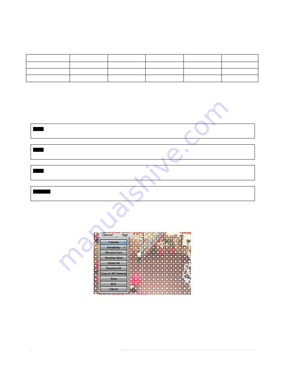
 The Motion Detection menu will allow user to set Motion detection alarm. 

 Press SETUP key (or right mouse button) and the SETUP menu will appear. 

 SETUP menu descriptions. 

-

 Camera: select camera for setup. 

-

 Sensitivity: select sensitivity (Low, Normal and High) 

-

 Reverse Vert: activate the entire column at the cursor’s position. 

-

 Reverse Horz: activate the entire row at the cursor’s position. 

-

 Select All: active all blocks. 

Summary of Contents for IQ-SDI-16

Page 1: ...nary information and is subject to change without notice Standalone Digital Video Recorder 4 8 16 Channel Models This document contains preliminary information and is subject to change without notice Standalone Digital Video Recorder 4 8 16 Channel Models This document contains preliminary information and is subject to change without notice Standalone Digital Video Recorder 4 8 16 Channel Models U...

Page 2: ...RITY TO OPERATE THE EQUIPMENT The equipment complies with the requirement of FCC CFR 47 PART 15 SUBPART B Class A Explanation of Graphical Symbols Warnings Installation and servicing should be performed only by qualified and experienced personnel Power off the DVR when connecting cameras audio or sensor cables The manufacturer is not responsible for any damage caused by improper use of the product...

Page 3: ...not place this equipment on an unstable cart stand or table The equipment may fall causing serious injury to a child or adult and serious damage to the equipment Wall or shelf mounting should follow the manufacturer s instructions and should use a mounting kit approved by the manufacturer Move this equipment and cart combination with care Quick stops excessive force and uneven surfaces may cause t...

Page 4: ...o determine that the equipment is in proper operating condition 16 Field Installation This installation should be made by a qualified service person and should conform to all local codes 17 Correct Batteries CAUTION RISK OF EXPLOSION IF BATTERY IS REPLACED BY AN INCORRECT TYPE DISPOSE OF USED BATTERIES ACCORDING TO THE INSTRUCTIONS 18 Operating Temperature An operating temperature range is specifi...

Page 5: ...l The List of Configuration DVR Set IQ SDI 4 Mini 4CH IQ SDI 8 16 Manual CMS CD Remote Controller Manual Screws HDD Brackets Except A Type Model Rack Bracket Except A Type Model Data Cable Power Cable Adapter Except D and E Type Models ...

Page 6: ... SETUP SYSTEM Information Status Setup Default HDD format HDD format is done by SETUP SYSTEM Admin Storage Format If there are more than two HDDs each must be formatted separately When the format is completed DVR will auto reboot Removal Follow the Remove procedure even when a pre installed hard disk has been removed SETUP SYSTEM Admin Storage Format click Removed item under the discrete Format he...

Page 7: ... 3 Front Panel 17 3 4 Using a Remote Controller 18 3 5 Using a Mouse 18 3 6 Screen Icon 19 4 SETUP 20 4 1 Login Logout 20 4 2 SYSTEM 21 4 2 1 Information 20 4 2 2 Admin 24 4 2 3 Account 26 4 2 4 System Log 29 4 2 5 Exit 29 4 2 6 Shutdown 29 4 3 DISPLAY 29 4 3 1 OSD 31 4 3 2 Main Monitor 31 4 3 5 VGA 32 4 4 DEVICES 32 4 4 1 Network 33 4 4 2 Camera PTZ 36 4 4 3 Audio 37 4 4 4 Alarm In 38 4 4 5 Alarm...

Page 8: ...8 P a g e Ness IQ SDI Users Manual NOTES ...

Page 9: ...DI 4 Known in this manual as Type A Power Supply Adapter DC 12V 5A and Power Supply Cable Ness IQ SDI 8 16 Known in this manual as Type B Power Supply Cable Remote Control With 2 AAA batteries Installation CD CMS Software User s Manual 1 2 Service If there is any problem in the product please refer servicing to a supplier or a distributor with qualified service personnel 1 3 System Connection Diag...

Page 10: ...10 P a g e Ness IQ SDI Users Manual Ness IQ SDI 8 16 Type B 8 16 channel Series HD ...

Page 11: ...s Part No 104 452 4 CH DVR Storage SATA 1 2 Port HDD 1 1 HDD Ness IQ SDI 4 Std Ness Part No 104 453 4 CH DVR Storage SATA 1 2 Port SATA 3 4 Port HDD DVD RW 1 2 3 4 1 1 HDD DVD RW 2 1 HDD HDD DVD RW 3 1 HDD HDD HDD DVD RW 4 0 HDD HDD HDD HDD Ness IS SDI 8 16 Ness Part No 104 451 8 Channel and 104 542 16 channel 8 16 CH DVR Storage SATA 1 2 Port SATA 3 4 Port SATA 5 Port HDD DVD RW 1 2 3 4 5 1 1 HDD...

Page 12: ...AT IS DONE BY SETUP SYSTEM ADMIN STORAGE FORMAT IF THERE ARE MORE THAN TWO HDDS EACH MUST BE FORMATTED SEPARATELY WHEN THE FORMAT IS COMPLETED DVR WILL AUTO REBOOT REMOVAL FOLLOW THE REMOVE PROCEDURE EVEN WHEN A PRE INSTALLED HARD DISK HAS BEEN REMOVED IN SETUP SYSTEM ADMIN STORAGE FORMAT CLICK REMOVED ITEM UNDER THE DISCRETE FORMAT HEADINGS OF A CORRESPONDING HDD TO DISCARD HDD ITEM WHEN THE REMO...

Page 13: ...OM IS NOT SUPPORTED ON THE LIVE SCREEN 2 2 4 Monitor Connections Video Out VGA HDMI and Spot Ness IQ SDI 8 16 Use computer monitor Connect the computer monitor to VGA or HDMI respectively 2 2 5 HDMI connections Connect HDMI cable to HD out port of rear panel and HDMI port of HD output device Please click SETUP DISPLAY VGA and the following screen will appear If user wishes to hear audio via HDMI c...

Page 14: ...k to archive data or a mouse to control the device 2 2 11 RS 232 Connections This port is not in use for users Do not connect any devices through this port CAUTION WHEN USING THE RS232 SERIAL PORT USERS MUST REQUEST FOR ASSISTANT TO QUALIFIED TECHNICAL PERSON OR SERVICE REPRESENTATIVE 2 2 12 Grounding Earthing Connection of ground wire is highly recommended to protect the DVR from external electri...

Page 15: ...wer supply the wall socket Input voltage is a free volt 100 VAC 240 VAC 2 2 15 Connections Guideline Video Out Connector If only the monitor is connected to VIDEO OUT connector please set the impedance switch on the rear side of the monitor to 75 ohms to prevent abnormally bright or collapsed images If wish to connect another device e g a recorder to the back of the monitor please set the impedanc...

Page 16: ... and then channel key ESC MENU Enter the Main Menu Setup mode REW Viewing mode Instant playback playback the recorded video from the last one minute Playback mode 1X PLAY PAUSE Zoom Out on PTZ mode BACKWARD Video search mode on off Zoom In on PTZ mode PLAY PAUSE Fast backward playback changes up to x128 with each press Focus Near in PTZ mode FORWARD Fast forward playback changes up to x128 with ea...

Page 17: ...ntrol the channels 3 3 Front Panel Ness IQ SDI 4 4 Channel DVR Ness IQ SDI 8 16 8 Channel DVR 16 Channel DVR 3 4 Using an IR Remote Control Usage of a remote controller is same as the front panel keys Follow the procedure below when using the remote controller for multi DVRs Check System ID e g between 1 and 255 of the DVR that wish to use SETUP SYSTEM Information Status System ID Holding up the r...

Page 18: ...ion Shutdown Pre step before Power off SETUP SYSTEM Shutdown PTZ En Disable PTZ control Cancel Cancel Function key menu Ness IQ SDI 8 16 Name of Key Function Name of Key Function Display Same as front key Event Same as front key indicate System Log Sequence Same as front key Search One touch playback same function with PLAY PAUSE Spot Same as front key Setup Same as front key Freeze Same as front ...

Page 19: ...lly following screen will appear Recording continues during setup Main menu consists of 5 sub menus SYSTEM DISPLAY DEVICES RECORD LINK There is no factory default in the case of passwords Factory default function cannot be applied to passwords To escape from the setup menu please click SYSTEM Exit on the screen Then the following dialogue box will appear Please choose OK to log out User may select...

Page 20: ...e whole sentence Please choose OK to confirm the input and choose Cancel to cancel System ID Control DVRs by one remote controller by setting DVR IDs Please click direction keys on the right hand side of the System ID frame to set the ID of DVR Take any whole number between 1 and 255 While pressing or button the System ID value increases or decreases by 10 units Language Please click Language fram...

Page 21: ...efault Import or Export process a message box will ask the progress and click the confirmation icon then a message box will show its success or failure When user complete Status data input please click Version and the following screen will appear Version Upgrade User may upgrade DVR software Please follow the Upgrade procedure below Plug USB memory stick having upgrade file into DVR Click Load fra...

Page 22: ...mation button and user may change the setting If user checks Disk full notify item the warning message will appear as the used amount of disk Used User may set the certain value of HDD usage for notification It will notify at that point The values are from 50 100 Alarm Out The Alarm out will happen at the used amount of HDD which is specified at Used Beep Check the warning sound will happen at the...

Page 23: ...x Y Year M Month and D Date Adjust the number by clicking buttons on the right hand side Repeat the same procedure to change Y M and D Time This menu will allow user to adjust the current time The adjustment procedure is same as of Date CAUTION IF ADJUSTED DATE TIME IS PRIOR TO RECORDED DATA DATA AFTER NEW DATE TIME MAY BE ERASED CAUTION ANY CHANGE IN DATE TIME IS IMMEDIATELY APPLIED ON VIEWING SC...

Page 24: ...in DVR User may check only one of Run as Server and Use NTP Run as Server NTP cannot be used in a non networked environment Intranet environment In this case DVR with Run as Server functions as Time Server Use NTP Connect to Internet to synchronize DVR clock with Network Time Server s clock When user completes NTP input please click to save the setup NTP Server Click keyboard icon in NTP Server fr...

Page 25: ...ort will allow users to connect up to maximum 12 HDD 1 DVD RW When user installs full storage device and DVD RW including two e SATA storage then following procedures will be listed as below 1 Internal SATA 1 4 Ports 2 External SATA 1 3 External SATA 2 4 Internal SATA 5 Port 5 DVD RW Format User must format when install new HDD add another HDD replace HDD move HDD change installation port remove H...

Page 26: ...en S M A R T function detects Abnormal symptoms from HDD Duration of alarm out operating time can adjust on DEVICES Alarm Out setup section please refer 4 4 5 Clicking direction buttons on the right hand of alarm out frame to select the device for alarm out Click direction buttons on the right hand side of Temperature frame to adjust to maximum temperature for the HDD used in DVR In general it is ...

Page 27: ...creen will appear Selectively enable password protection for important operations Setup Search Network Archiving and Shut Down Please check the operations that wish to enable password protection CAUTION USER WILL NOT BE ASKED TO ENTER YOUR PASSWORD FOR OPERATION S WHERE PASSWORD PROTECTION IS NOT ENABLED Choose OK to confirm the setting Please click New User and the following screen will appear Cl...

Page 28: ...lows Click to delete the set Group or User User may create up to 8 Groups and 8 Users Choose OK to confirm the setting Password Resetting Click ID on User column The following screen will appear This is a screen for password resetting Input password by clicking the keyboard icon on the right hand side of the frame ...

Page 29: ...M A R T Check NTP Sync Server Success Fail Send E mail Success Fail HDD Format Success Fail Data clear Success Fail USB Upgrade Success Fail DVR Setup Change by Remote Before After Time Adjust System Log removal procedure is as follows Execute Clear All Data in SYSTEM Information Record and choose OK on the popup dialogue box Please note that all normal recorded video data are deleted from databas...

Page 30: ... on the dialogue box to confirm When user select Shutdown menu the OSD menu on the screen disappears Reboot the DVR after Shutdown Turn off the DVR and wait for 5 seconds before restart 4 3 DISPLAY Please click DISPLAY and the following screen will appear 4 3 1 OSD Please click DISPLAY OSD and the following screen will appear The OSD menu will allow user to configure full features i e on off every...

Page 31: ...he camera that wish to include in sequencing Any camera with unchecked check box will be excluded from channel sequencing Adjust the rotation interval of camera by clicking Dwell column The rotation interval changes to 3 5 10 15 30 60 seconds by each press Use only with 8 16 channel DVRs Adjust interval for X4 Split Screen sequencing Check check box next to the camera that wish to include in seque...

Page 32: ...tput will help users to select its video output between NTSC and PAL HD SDI DVR Once it has changed it will ask to reboot for the new recognition of video out method The default value is NTSC CAUTION ALTHOUGH USERS TURN ITS SYSTEM SETTING TO DEFAULT THE ANALOG OUTPUT WILL STAY PREVIOUS OUTPUT METHOD AND NOT EFFECT BY THE DEFAULT SETTING 4 4 DEVICES Please click DEVICES and the following screen wil...

Page 33: ... on the right hand side of each frame In DHCP IP Address Subnet Mask Gateway and DNS Server will have input automatically DNS Server When user set Network Type to DHCP DNS server will be inputted automatically When user set Network Type to Static please click the keyboard icon on the right hand side of DNS Server frame and manually input the address CAUTION NOTE THAT DNS SERVER ADDRESS IS IP ADDRE...

Page 34: ... 95 will be shown as default If 95 is unable please consult with a product distributor When user press Get Domain Name button Domain Name and MAC Address value will automatically display after 10 seconds Choose OK to confirm the setting 3rd Party Check a checkbox of 3 rd Party to use dyndns org or no ip com Server As for DDNS Server dyndns org will be showing as default No ip com can be selected b...

Page 35: ...er for Video Audio and Web Port The Port Number Setup menu has two selections of Register UPNP or Unregister UPNP Click Register UPNP for automatic port forwarding Click Unregister UPNP to do port forwarding manually For Port Number Setup please get an approval of the network administrator in connection with CMS program Port number Administrator 5000 65535 Video Audio 5000 65535 Web 1 65535 Choose...

Page 36: ...replaceable When an event occurs users can send an email to a designated mail address by clicking attach button and selecting data to be transmitted Users may select one of JPEG VIDEO CLIP and None In case of transmitting VIDEO CLIP data set the duration of time for recoded data in duration menu e g 1 sec 3 sec 5 sec CAUTION ACCORDING TO THE VARIOUS LOCAL CONDITIONS SSL EMAIL SERVERS MAY NOT WORK ...

Page 37: ...he OSD menu even in DVR If OSD enter command is 95 PSET for example designate 95 for Menu item If shortcut key to use Tour function is 71 79 PSET designate 70 for Tour item and If shortcut key to use Pattern function is 81 89 PSET designate 80 for Pattern item The setting information herein is used for PAN TILT control in 5 1 5 to be described If click Default basic setup values are given i e Menu...

Page 38: ... does not check the check box the operation stops Click each frame on Type column to select type of a corresponding Alarm input NO contact is normally open Normally open NC contact is normally closed Normally closed User may change the type of all Alarm input at a time by clicking the Type box on the menu tab Choose OK to confirm setting 4 4 5 Alarm Out Please click DEVICES Alarm Out and the follo...

Page 39: ... closed User may change the type and duration of all Alarm output at a time by clicking the Type and Duration box on the menu tab Choose OK to confirm setting 4 4 6 Serial In NOTE Please refer to 14 Serial In 4 5 RECORD Please click RECORD and the following screen will appear ...

Page 40: ...Channel Max 7 fps per Channel 8 Channel DVR Max 25 fps per Channel Max 25 fps per Channel Max 25 fps per Channel Max 12 fps per Channel Max 7 fps per Channel 16 Channel DVR Max 12 fps per Channel Max 12 fps per Channel Max 12 fps per Channel Max 7 fps per Channel Max 7 fps per Channel Click each frame on Quality column to select recording quality of a corresponding camera User may select its recor...

Page 41: ... 12 fps per Channel Max 7 fps per Channel Max 7 fps per Channel Click each frame on Quality column to select recording quality of a corresponding camera User may select its recording quality from Super High and Std Click each frame on Duration column to select recording duration i e 1 second 3 hours of a corresponding camera User may change the setting values of Resolution Frames Quality and Durat...

Page 42: ...User may change the setting values of Resolution Frames Quality and Duration at a time by clicking the menu tab Choose OK to confirm the setting NOTE The maximum recording frame is varied from different types of HD SDI signal which can be input in to a DVR NOTE A B Types of DVR will detect 1080i 1080p or 720p HD SDI input signals automatically while it is booting Auto Detection NOTE For 1080i sign...

Page 43: ...Motion Alarm In Continuous Motion Alarm In PreAlarm Choose OK to confirm the setting NOTE Holiday H registration is done with a separate menu 4 5 3 Pre Alarm Please click RECORD Pre Alarm and the following will appear Pre Alarm is effectively used when user selected recording mode by Alarm or Motion The Pre Alarm will allow user to check during playback the previously recorded video before the rec...

Page 44: ...ame on Duration column to select recording duration i e 1 second 3 hours of a corresponding camera User may change the setting values of Resolution Frames Quality and Duration at a time by clicking the menu tab Choose OK to confirm the setting NOTE The maximum recording frame is varied from different types of HD SDI signal which can be input in to a DVR NOTE A B Types of DVR will detect 1080i 1080...

Page 45: ... arrow buttons in the Month Calendar to select Year and Month of holiday to be registered search subsequent Year search previous Year search subsequent Month search previous Month Click on date user need to register as holiday Click ADD button and the date just clicked on will be copied to the Schedule frame for registration If wish to cancel the registration of a certain holiday please click butt...

Page 46: ...s to be worked when Alarm In 1 is on Please check a check box under Link Alarm Out More than two alarm outputs can be set Select E mail addresses for notification when Alarm In 1 is on Please check a check box under Link Notification More than two E mail addresses can be set Repeat the above procedure for Alarm In 2 Alarm In 16 2 for IQ SDI 4 Channel Up to 16 for IQ SDI 8 16 Channel Choose OK to c...

Page 47: ... Loss and the following screen will appear Select cameras for recording while the motion sensor is in operation and alarm outputs and set up E mail addresses for notification Link Notification displays E mail addresses registered in DEVICES Network Notification Please follow the setup procedures below Click Video Loss frame and select Video Loss 1 Select cameras for recording when Video Loss 1 is ...

Page 48: ... can be set Select E mail addresses for notification when emergency occurs Please check a check box under Link Notification More than two E mail addresses can be set Choose OK to confirm the setting 4 6 5 Popup Link Please click LINK Popup Link and the following screen will appear When Motion or Alarm In is detected user can select a popup or beep sound for warning or have a particular channel of ...

Page 49: ...io recording 16 CMS Access Indication No of accesses up to 16 In channel sequencing Setup in HDD Overwrite mode Setup in HDD None Overwrite mode recording Setup in HDD None Overwrite mode HDD Full On the right bottom side of the screen disk usage will show by On the left low side of the screen icon will show as the progress At the normal state HDD Overwrite mode is on and icon shows When Overwrite...

Page 50: ... SEQUENCE key to display images in sequencing view format periodically This automatic sequence function is not limited to the full screen format but can be used in any view mode In the 8 channel DVR 4 camera sequencing view mode is possible and in the 6 channel DVR 4 or 9 camera sequencing view modes are possible 5 1 3 Digital Zoom Select a Channel into Full Screen Drag a portion to zoom by mouse ...

Page 51: ...eset select preset No and button click Available 1 255 Preset numbers can saved it depends on camera specification As explained earlier in 4 4 2 press Menu button to pop up PTZ camera OSD setup screen and set up Tour and Pattern items Since these functions make use of a memory function of the camera itself user should set them in Camera OSD Once user completes the setup close the Camera OSD menu U...

Page 52: ...ower portion on the right hand side of the screen Once the Key Lock function is activated user cannot use any key If wish to use a key please enter the correct password to release the key lock function If Password is not required simply press ENTER key 5 1 8 Emergency Recording When user presses EMERGENCY key recording starts right away regardless of preset recording mode Emergency recording is no...

Page 53: ...onfirm the setting Then the selected video will be played back Playback continues from the designated time until the last recording time 5 2 2 Calendar Search Please click Calendar Search in SEARCH menu and the following input box will appear Dates and Time with recorded data available will be high lighted Follow the procedure below to search video by calendar Select Year and Month by using the ar...

Page 54: ...signated time until the last recording time NOTE Click search button to show entire channel search based on different time frames 5 2 3 Event Search Please click Event Search in SEARCH menu and the following input box will appear This involves searching recorded video to playback the selected video of a specific date and time Press SEARCH key on the viewing screen or use the mouse wheel central bu...

Page 55: ...t screen format To change the viewing mode please press DISPLAY key or Camera Select key 1 16 NOTE Using a mouse Double click to view the full screen and double click one more time to back to Split Screen Move the cursor of the mouse and the keypad control will appear at the bottom near the center of the screen Every time user presses the PLAY PAUSE key during playback mode it is changed to 1X PLA...

Page 56: ...right hand side of FROM frame to set the storage start time Click the keyboard display on the right hand side of TO frame to set the storage end time Click Destination frame to select a storage device out of USB and DVD RW Click the keyboard display on the right hand side of File Name frame to input a file name User does not need to input extension exe jpeg Please note that the file is not going t...

Page 57: ...Time indication then Menu bar will show up on the live screen Each icon functions as below Exit the Menu Bar Safely turn off the DVR Enter Archive mode Enter PTZ control mode Enter Setup mode Turn the display as 1 channel full screen Additional click on full screen it will change to next channel in sequence Turn the display as 4 channels split screen Additional click will change to the next four c...

Page 58: ...ERS TURN ITS SYSTEM SETTING TO DEFAULT THE ANALOG OUTPUT WILL STAY PREVIOUS OUTPUT METHOD www nesscorporation com HEAD OFFICE Ness Corporation Pty Ltd ABN 28 069 984 372 Phone 61 2 8825 9222 Fax 61 2 9674 2520 Sydney Ph 02 8825 9222 Fax 02 9674 2520 sales ness com au Melbourne 874 6400 nessmelb ness com au Brisbane 399 4910 essbris ness com au PERTH 8 9328 2511 essper ness com au Adelaide 152 0000...

Reviews: