


Nuvo-7160GC/ Nuvo-7164GC Series
29
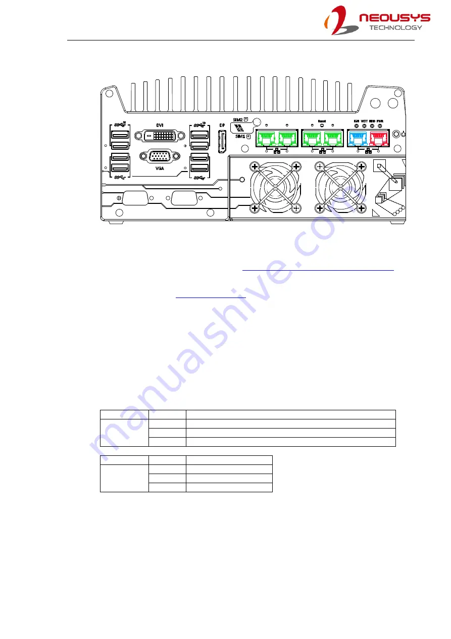
2.3.7
Ethernet Port/ PoE+
The ports marked in
green
(with optional PoE)
and
red
implemented using Intel
®
I210 while
the port marked in
blue
is implemented using Intel
®
I219-LM controller that supports
Wake-on-LAN and is also compatible with
AMT (Active Management Technology)
support advanced features such as remote SOL desktop and remote on/ off control. All
Ethernet ports feature
Power over Ethernet (PoE) supplies electrical power and data on a standard CAT-5/ CAT-6
Ethernet cable. Acting as a PoE PSE (Power Sourcing Equipment), compliant with IEEE
802.3at, each PoE port delivers up to 25W to a Powered Device (PD). PoE can automatically
detect and determine if the connected device requires power or not, so it is compatible with
standard Ethernet devices as well.
Each port has one dedicated PCI Express link for maximum network performance. Please
refer to the table below for LED connection statuses.
Active/Link LED (Right)
LED Color
Status
Description
Yellow
Off
Ethernet port is disconnected
On
Ethernet port is connected and no data transmission
Flashing Ethernet port is connected and data is transmitting/receiving
Speed LED (Left)
LED Color
Status
Description
Green or
Orange
Off
10 Mbps
Green
100 Mbps
Orange
1000 Mbps
To utilize the GbE port in Windows, you need to install corresponding driver for Intel
®
I210-IT/
I219-LM GbE controller.
Summary of Contents for Nuvo-7160GC Series
Page 1: ...Neousys Technology Inc Nuvo 7160GC Series Nuvo 7164GC Series User Manual Revision 1 0...
Page 17: ...Nuvo 7160GC Nuvo 7164GC Series 17 1 2 3 Nuvo 7160GC Top View...
Page 18: ...Nuvo 7160GC Nuvo 7164GC Series 18 1 2 4 Nuvo 7160GC Bottom View...
Page 20: ...Nuvo 7160GC Nuvo 7164GC Series 20 1 3 3 Nuvo 7164GC Top View...
Page 21: ...Nuvo 7160GC Nuvo 7164GC Series 21 1 3 4 Nuvo 7164GC Bottom View...
Page 84: ...Nuvo 7160GC Nuvo 7164GC Series 84 4 Remove the Cassette module cover and bezel cover s...
Page 146: ...Nuvo 7160GC Nuvo 7164GC Series 146 7 Follow the 6 step setup procedure as instructed...
Page 148: ...Nuvo 7160GC Nuvo 7164GC Series 148 9 When done click on Finish and restart the system...


