background image


Page 10 


09604-ML001 REV01 ECN 5297  


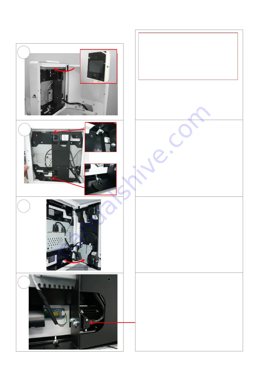
2.3  Replacing the Camera


STEP 1   

Unlock and open the LCD door by 

unlocking the Lock at the front right hand side 
of the LCD door . 
The door can now be opened by grasping the 
top right corner and pulling open. 

STEP 2   

Loosen the 2 wing nuts at the top an 

bottom of the Camera mount bracket. 

STEP 3   

The Camera mount door can now be 

opened by grasping the bottom left corner and 
pulling open. 

STEP 4   

Unplug the cable from the back of the 

camera 

CAUTION: Servicing of this product or unit is to 

be performed by trained service personnel only. 

Chapter 2 - Servicing


Caution : 

This Kiosk is equipped with an 

Uninterruptable Power Supply (UPS) 
Prior to service by service by a certified 
technician, for operator safety, ensure mains 
cable is disconnected from the kiosk and the 
UPS is switched OFF   Refer Section 2.0 
Powering OFF procedure. 

Summary of Contents for 09604

Page 1: ...09604 ML001 REV01 ECN 5297 09604 E Border Kiosk SERVICE MANUAL...

Page 2: ...Page 2 09604 ML001 REV01 ECN 5297 Version History ISSUE NUMBER DATE ECN COMMENTS APPROVED 1 0 29 05 19 5297 KJR...

Page 3: ...Procedure 6 2 1 PC Reset Switch 7 2 2 Replacing the LCD Screen Module 8 2 3 Replacing the Camera 10 2 4 Replacing the Power Data Panel Kit 12 2 5 Replacing the Access door 14 2 6 Replacing the Passpo...

Page 4: ...ts may use or distribute any of the information you supply in any way it believes appropriate without incurring any obligation to you Any references in this information to non Neo Products Web sites a...

Page 5: ...l cables Never turn ON any equipment when there is evidence of fire water or structural damage Sharp edges corners and joints may be present in and around the system Use care when handling equipment t...

Page 6: ...ted from the kiosk and the UPS is switched OFF STEP 4 To power OFF the UPS Press the button Press the button again to power ON then Close and lock the Access Door STEP 1 The AC mains power cord of the...

Page 7: ...rvicing of this product or unit is to be performed by trained service personnel only STEP 2 Place the Key in the lock Turn the Key and release to reset the PC STEP 1 The PC Reset Switch is located in...

Page 8: ...en STEP 2 Loosen the 2 wing nuts at the top and bottom of the Camera mount bracket STEP 3 The Camera mount door can now be opened by grasping the bottom left corner and pulling open STEP 4 Unplug the...

Page 9: ...EP 6 Lift the screen off the Kiosk hinges STEP 7 Place the replacement screen on the hinges and connect the door stay to the kiosk STEP 8 Reconnect the cables to the LCD and secure them in the cable c...

Page 10: ...Camera mount door can now be opened by grasping the bottom left corner and pulling open STEP 4 Unplug the cable from the back of the camera CAUTION Servicing of this product or unit is to be performe...

Page 11: ...emove the Camera STEP 7 Place the new Camera and secure with the 2 screws 7 8 STEP 8 Plug the cable into the back of the camera Close the Camera mount door and retighten the 2 wing nuts to secure the...

Page 12: ...Right Hand Side door Unlock the Lower Lock at the front of the door and pull the top corner of the door to open STEP 4 Unplug the Molex connectors and Disconnect all the cables from the rear of the Po...

Page 13: ...he assembly from the Kiosk STEP 8 Replace the Power Data Panel Assembly with the new module by reversing the steps 1 to 6 Close and lock the Kiosk door 7 CAUTION Servicing of this product or unit is t...

Page 14: ...or similar tool to hook under it STEP 4 Lift the door up and off the hinge pins to remove it from the kiosk STEP 2 With the door unlocked but Closed locate the hinge pin of the Bottom door hinge Hinge...

Page 15: ...in handle away from you to latch the hinge If replacing the Left hand door rotate the latch securing the Left hand door Close and Lock the right hand door STEP 5 Place the new Access Door onto the Kio...

Page 16: ...open STEP 1 You need to unlock and open both Access Doors to open the Passport top cover Unlock the Lower Lock at the front of the right hand door and pull the top corner of the door to open 3 4 STEP...

Page 17: ...s Door and from inside the kiosk rotate the latch to secure the door Refer step 2 Close and lock the right hand Kiosk Access Door STEP 7 Unlatch the passport cover stay by lifting the Passport Top Cov...

Page 18: ...g the side tab into the chassis vertical slot and inserting the tab at the base of the door into the bottom opening in the chassis Secure the Printer door with the 2 screws removed in step 2 STEP 2 Un...

Page 19: ...rs STEP 4 Remove the Printer door from the Zepatronics kit Refit the Printer door to the Kiosk as per Section 2 6 STEP 2 Undo the 2 front screws that secure the Printer door STEP 1 Unlock and open the...

Page 20: ...is equipped with an Uninterruptable Power Supply UPS Prior to service by service by a certified technician for operator safety ensure mains cable is disconnected from the kiosk and the UPS is switched...

Page 21: ...y trained service personnel only STEP 5 Open the Power Data Panel Assembly door STEP 6 Undo the 2 screws securing the strap holding the UPS in position Remove it from the Kiosk Replace the UPS with th...

Reviews: