


Chapter 3 Connectors
30
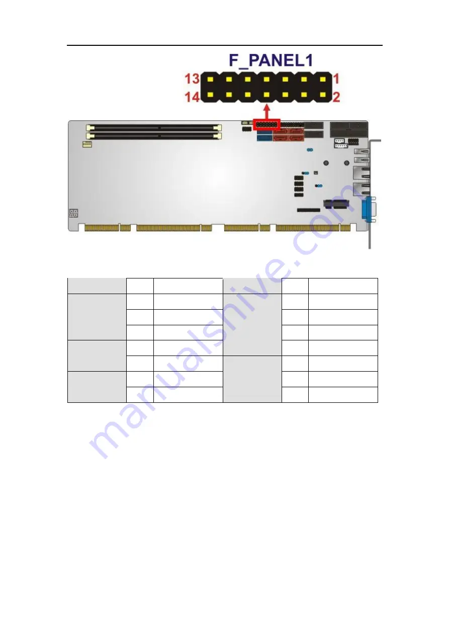
Figure 3-9: Front Panel Connector Location
FUNCTION
PIN
DESCRIPTION
FUNCTION
PIN
DESCRIPTION
Power LED
1
+5V
Speaker
2
+5V
3
N/C
4
N/C
5
GROUND
6
N/C
Power Button 7
8
Speaker
9
PWR_BTN-
Reset
10
N/C
HDD LED
11
+5V
12
RESET-
13
HDD_LED-
14
GROUND
Table 3-9: Front Panel Connector Pinouts
3.2.9
I
2
C Connector
CN Label:
I2C_1
CN Type:
4-pin wafer
CN Location:
See
Figure 3-10
CN Pinouts:
See
Table 3-10
The I2C connector is for system debug.


