


Chapter 3 Connectors
29
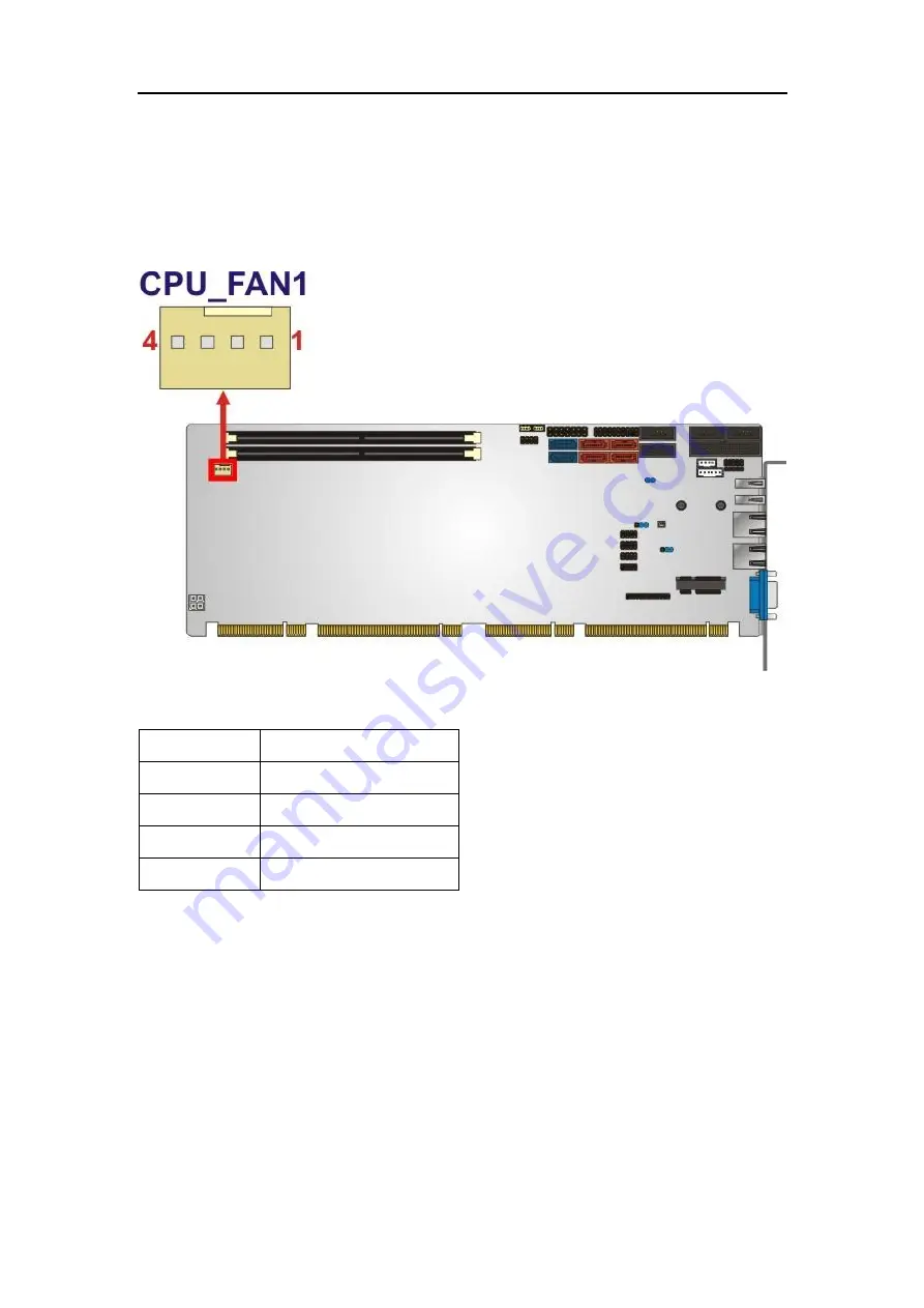
CN Type:
4-pin wafer
CN Location:
See
Figure 3-8
CN Pinouts:
See
Table 3-8
The fan connector attaches to a CPU cooling fan.
Figure 3-8: CPU Fan Connector Location
PIN NO.
DESCRIPTION
1
GND
2
+12 V
3
Rotation Signal
4
PWM Control Signal
Table 3-8: CPU Fan Connector Pinouts
3.2.8
Front Panel Connector
CN Label:
F_PANEL1
CN Type:
14-pin header
CN Location:
See
Figure 3-9
CN Pinouts:
See
Table 3-9
The front panel connector connects to the indicator LEDs and buttons on the
computer's front panel.


