


Tucker GmbH,
Mail / Post:
Max-Eyth-Str.1, 35394 Gießen, Germany
Stud welding unit N800i
As of 24.08.2021
Manual part number: BE 1227
89
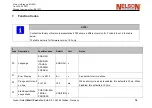
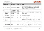
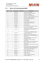
Error Number
Error Display
What this really means
Fatal
–
meaning you
have to power down
to reset. Otherwise,
you weld again to
reset.
Likely problem
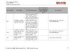
E005
REGULATION
ERROR‐
SHORT CIRCUIT‐
COULDN’T CONT‐
ROL CURRENT
The control sensed that the
current was more than 50%
high and the control is ap‐
plying the minimum allo‐
wable pulse width for 10ms.
Current sensor wiring or dead short circuit
‐See
troubleshooting‐
E006
INPUT VOLTAGE TOO
HIGH
This happens if the capaci‐
tor voltage exceeds 400V
due to capacitor imbalances.
This also happens on boot‐
up if the voltage skyrockets
after closing relays.
x
Input voltage is too high
‐See
troubleshooting‐
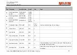
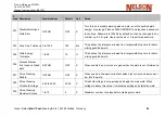
E007
INPUT VOLTAGE TO
LOW‐FLIP
SWITCH TO
CORRECT VOLTAGE
SETTING
On boot‐up only, after clo‐
sing the charge relay, the
caps have 10 seconds to get
the proper voltage.
x
Incorrect voltage setting or broken/bad
V‐
F signal from one or more switch boards.
‐See
troubleshooting‐
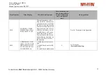
E008
PRIMARY
OVERCUR‐
RENT ERROR
A primary overcurrent
oc‐
curred.
x
On‐board
control PCB failure
‐See
troubleshooting‐
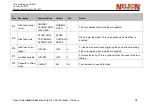
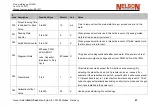
E009
COULD NOT ES‐
TABLISH PILOT ARC
The gun did not lift within
the pilot arc period
Shorted gun control cable, mechanical
bin‐
ding of the gun, pilot arc pcb failure, or
ex‐
cessive contaminants on work surface.
‐See
troubleshooting‐
E010
CAPACITOR VOL‐
TAGE COULD NOT BE
READ
The sensed capacitor
V‐F
si‐
gnal is not within
the ac‐
ceptable bounds.
Check
V‐F
signal from Switch Boards
‐See
troubleshooting‐
Summary of Contents for N800iTM
Page 18: ......