


Tucker GmbH,
Mail / Post:
Max-Eyth-Str.1, 35394 Gießen, Germany
Stud welding unit N800i
As of 24.08.2021
Manual part number: BE 1227
4
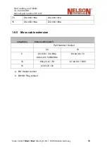
1.4
Operational Sequence
When welding in keeping with the drawn
‐
arc method the gun must be loaded with a stud
and a ceramic ferrule. When welding in keeping with the short
‐
cycle method the ceramic
ferrule is usually not used.
The loaded gun is pressed onto the workpiece at a right angle until the supporting tube
touches the workpiece. The stud projecting from the supporting tube is pushed back at
the same time compressing the pressure spring of the gun.
When the weld command is given, a pilot arc flows along the short
‐
circuit distance
between the stud and the workpiece. The gun coil lifts the stud from the workpiece
against the force of the compressed spring.
When the welding stud is lifted from the workpiece, an pilot arc is drawn to begin with
and then the main arc is ignited.
During the travel motion the arc melts the end of the stud and an ap proximately equally
sized area on the workpiece so that a pool of liquid metal is formed under the arc and the
stud.
As soon as the gun coil is switched off
‐
circuit the stud accelerates back onto the
workpiece as a result of the force of the pressure spring.
Once the stud plunges into the weld pool, the main arc extinguishes and the weld
current is switched off. The stud is pressed into the still liquid molten mass before the
weld pool solidifies.
The gun is removed from the stud. When welding with ceramic fer
‐
rules the latter must
be knocked off the cooled stud.
Welding sequence diagram:
1. Placing
the
welding
stud
2. Drawing
the
auxiliary
arc
3. Igniting the
main arc
4. Immersing
the welding
stud
5. End of welding
The weld time as per per drawn
‐
arc method is approx. 100ms
‐
1000ms.
Summary of Contents for N800iTM
Page 18: ......