Disassembly Guide
60
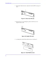
9. Remove the bracket and screw connected to the front PCB. See Figure 19
item 1.
Figure 19: Front Case Bracket
10. Remove the two screws holding the speaker to the front case. See
Figure 20 items 1 and 2.
Figure 20: Speaker Removal
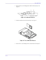
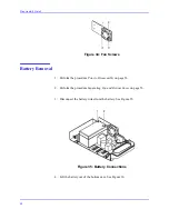
11. Carefully lift the front PCB out of the front case. See Figure 21.
Figure 21: Front PCB Removed
Summary of Contents for OxiMax N-550
Page 1: ...N 550 Pulse Oximeter Service Manual min min SpO2 N 550 SatSeconds SpO2 ...
Page 10: ...Blank Page ...
Page 38: ...Blank Page ...
Page 64: ...Blank Page ...
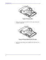
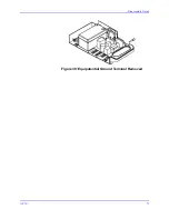
Page 81: ...Disassembly Guide N 550 71 Figure 39 Equipotential Ground Terminal Removed ...
Page 82: ...Blank Page ...
Page 86: ...Spare Parts 76 Figure 40 Exploded View ...
Page 90: ...Blank Page ...
Page 108: ...Blank Page ...
Page 120: ...Blank Page ...
Page 130: ...Figure 56 Main PCB Parts Locator Diagram 129 Technical Description N 550 ...
Page 131: ...Figure 57 Front Panel Parts Locator Diagram 131 N 550 Technical Description ...
Page 136: ...Blank Page ...
Page 137: ... ...


