background image

Press On/Off switch push forward to lock position, then release the On/Off switch. 
The angle grinder will continue to operate until the on/off switch is released.   
To release the on/off switch, just press switch again. It will return to original 
position 

 
CAUTION! 

Always carry out a test run before starting work and after every tool 

change! Always ensure that the tools are in good condition, correctly mounted 
and able to turn freely. The trial run should be at last 30 sec. 


WARNING


Vibrating discs must be replaced immediately.   

Please always keep other persons and combustible material from work area. 
Please always make sure work with guard and disc in position before start the 
machine. 

 
Mounting disc 

The mounting hole of disc must fit with the mounting flange. Do not use reducers 
or adapters. 
The direction-of-rotation arrow on disc and machine (see direction-of-rotation 
arrow on the machine head) should be same. 
 

CAUTION!  

Never use discs whose diameter is larger than that indicated.   
The maximum rotation speed of disc must be greater than the idling speed of the 
machine. 
 

CAUTION! 

Never use the grinding disk for cutting 

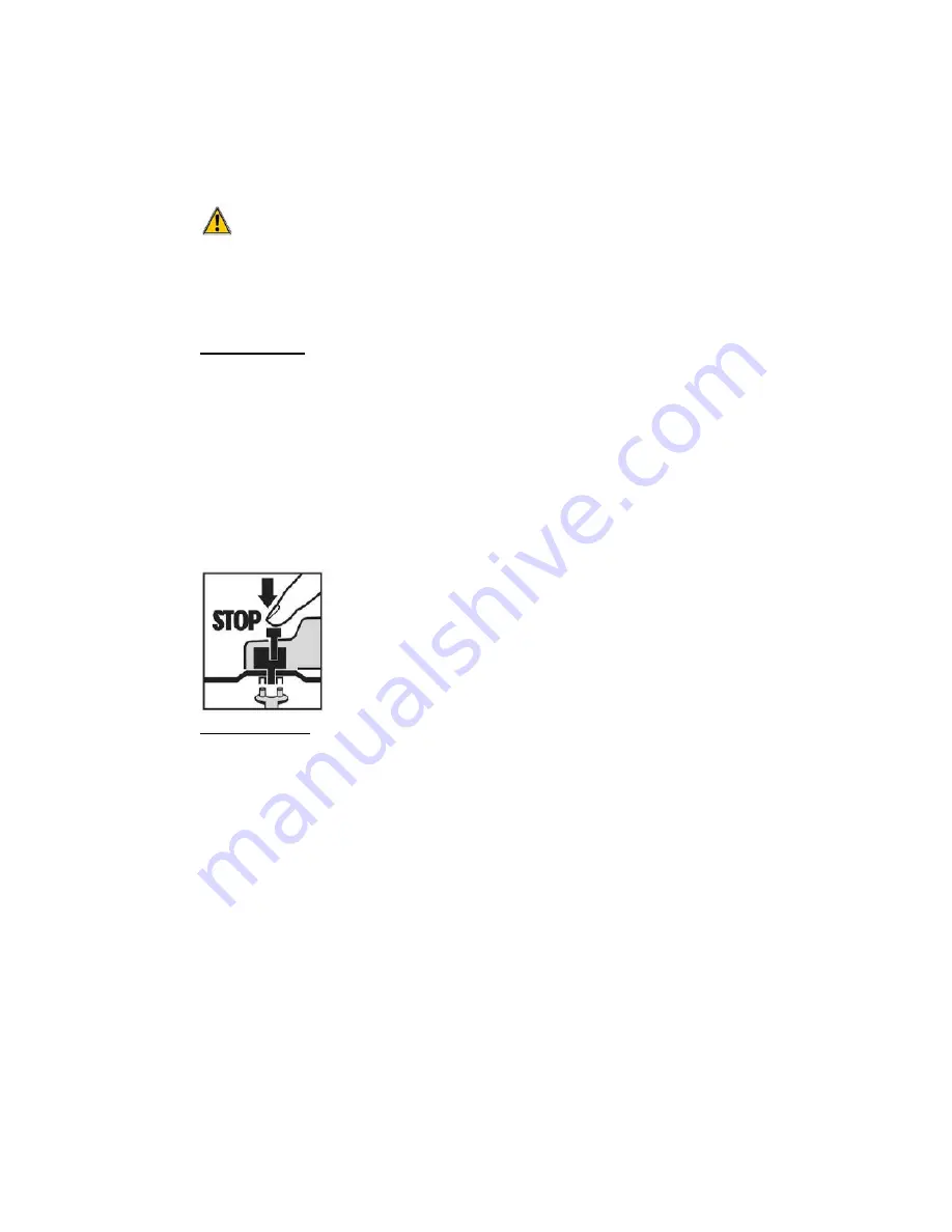
To assembly the disc, press the spindle-lock button in deep 
and hold it in this position continuously. If necessary, turn the 
spindle slightly with the free hand until it locks into position.   
 
And then put the disc between two flanges and then tighten 
the outer flange with the spanner provided. 


Removing disc 

To remove the disc, press the spindle-lock button in deep and hold it in this 
position continuously. If necessary, turn the spindle slightly with the free hand until 
it locks into position.   
Loose the flange with the spanner provided and then removes the disc from 
spindle. 

Summary of Contents for CT0827

Page 1: ...DER CT0827 ORIGINAL INSTRUCTIONS Cannon Tools Limited Address 20 Station Road Rowley Regis West Midlands B65 0JU UNITED KINGDOM SAVE THESE INSTRUCTIONS AND PRECAUTIONS READ ALL PRECAUTONS AND INSTRUCT...

Page 2: ...In case of alteration of the machine not agreed upon by us this declaration will lose its validity Product description ANGLE GRINDER Model CT0827 Applicable EC Directives EC Machinery Directive 2006 4...

Page 3: ...achine is designed with double insulation It is not necessary to connect it to an earthed power socket This symbol indicates the requirement of wearing ear protection eye protection when using the pro...

Page 4: ...oidable use a residual current device RCD protected supply Use of an RCD reduces the risk of electric shock 3 Personal safety a Stay alert watch what you are doing and use common sense when operating...

Page 5: ...to operate the power tool Power tools are dangerous in the hands of untrained users e Maintain power tools Check for misalignment or binding of moving parts breakage of parts and any other condition...

Page 6: ...ssories mounted by flanges the arbour hole of the accessory must fit the locating diameter of the flange Accessories that do not match the mounting hardware of the power tool will run out of balance v...

Page 7: ...pinning accessory could snag your clothing pulling the accessory into your body n Regularly clean the power tool s air vents The motor s fan will draw the dust inside the housing and excessive accumul...

Page 8: ...arp edges etc Avoid bouncing and snagging the accessory Corners sharp edges or bouncing have a tendency to snag the rotating accessory and cause loss of control or kickback e Do not attach a saw chain...

Page 9: ...other masonry products and arsenic and chromium from chemically treated lumber Your risk from these exposures varies depending on how often you do this type of work To reduce your exposure to these ch...

Page 10: ...tool However if the tool is used for different applications with different accessories or poorly maintained the vibration emission may differ This may significantly increase the exposure level over t...

Page 11: ...he disc guard can be adjusted to suit the working conditions To do this please follow below steps 1 Loosen the hexagon bolt with the spanner 2 Turn the guard to the desired position 3 Retighten the he...

Page 12: ...ting flange Do not use reducers or adapters The direction of rotation arrow on disc and machine see direction of rotation arrow on the machine head should be same CAUTION Never use discs whose diamete...

Page 13: ...dents are caused by heavy wheels being fitted to spindles designed to take only the lightest of wheels As a result vibration is excessive and breakages occur On no account should an abrasive wheel be...

Page 14: ...a tool Follow theinstructions in the maintenance section of this user manual Caution If the tool s power cord is damaged it must be replaced with a specially manufactured cable available from the aft...

Page 15: ...PARTS DIAGRAM...

Page 16: ...2 bearing 6000 1 41 spring 2 13 bearing plate 1 42 brush holder 2 14 screw M4 x 12 3 43 carbon brush 2 15 output spindle 1 44 brush cover 2 16 half key 2 45 wire plate 1 17 super gearing 1 46 screw ST...

Page 17: ...CANNON TOOLS LTD Add 20 station road Rowley Regis west midlands B65 0JU U K Made in China...

Reviews: