Neets Control – SieRRa II
SieRRa II EU P/N: 310-0102
SieRRa II DK P/N: 310-0202
SieRRa II US P/N: 310-0402
User Manual
Page 1: ...Neets Control SieRRa II SieRRa II EU P N 310 0102 SieRRa II DK P N 310 0202 SieRRa II US P N 310 0402 User Manual...
Page 2: ...ts dk or you may use our contact form at www neets dk Revision list This document no 310 0102 001 009 001 has the following revision changes Author Date Description Pages Rev MH 10 06 2015 First relea...
Page 3: ...components inside These openings must never be blocked by other objects Do not use this equipment near water To reduce the risk of fire or electric shock do not expose this apparatus to rain or moistu...
Page 4: ...ontents 4 Description 5 Quick guide to the SieRRa II 6 Installation 7 Connections and Controls 9 Power input port 9 I O ports 9 RS 232 IR port 9 NEB port 10 LAN port 11 Buttons 11 Configuration throug...
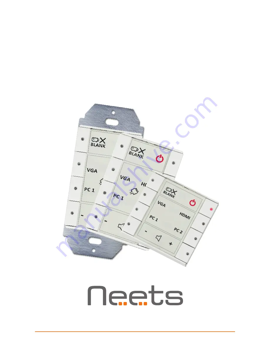
Page 5: ...y to install SieRRa II can control devices through IR RS232 or even LAN SieRRa II is available in polar white and anthracite The drawings in the manual of Neets Control SieRRa II is based on the DK US...
Page 6: ...x RS 232 or IR ports Unidirectional 4 1 x RJ 45 Network LAN connector with PoE functionality 5 3 x Digital Input Output 6 1 x NEB bus port 1 A V MUTE OFF DVD PC 1 BLUERAY PC 2 SCREEN 3 2 1 2 Neets Con...
Page 7: ...ystem in the back box or on the bracket DK version Insert a flathead screwdriver gently and pry out the front cover Remove the front cover and the paper label behind it Insert a flathead screwdriver i...
Page 8: ...sert a flathead screwdriver gently and pry out the front cover Remove the front cover and the paper label behind it Insert the control system in a frame matching the back box used Insert screws matchi...
Page 9: ...nection to a PIR movement sensor keyboard lock relays or for other compatible uses The ports are not potential free you may need external relays to prevent ground loops depending on your application W...
Page 10: ...er Connect your NEB devices to this port with a cable not exceeding 20 cm of length Connec tions are PWR to PWR NCL to NCL NDA to NDA and GND to GND If additional cable length is needed in your applic...
Page 11: ...r LED light to indicate current status of the AV system Button function and LED indication are set up using the Neets Project Designer software Configuration through USB port The USB port is used excl...
Page 12: ...In this case try uploading an empty project and see if this works 1 Flashing 2 Flashing 3 Off 4 Off Unexpected Error o Turn off the power to the control system for 20 sec before turning the power on a...
Page 13: ...Output Ports 3 x I O Input trigger low 1VDC Input trigger high 4VDC Output type Open drain Isolated output No Max voltage load 24 VDC Max current 0 5 A Connector 4 pin screw block Network LAN Speed 1...