Fan Inverter
5 Pressure control
Nederman Fan Inverter uses an integrated pressure sensor and pressure taps in the duct work. This makes the
system operate more efficiently by measuring the system pressure, and adjust the fan speed in order to main-
tain a constant pressure. If the system pressure is low, Fan Inverter can increase its fan speed and vice versa.
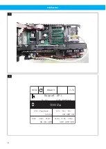
5.1 Pressure sensor
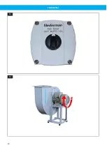
See
from the most distant extraction point in the duct system, or at the extraction unit that creates the highest
pressure drop.
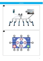
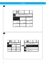
The pressure value for the system is then displayed through the unit’s integral PID controller. The actual pres-
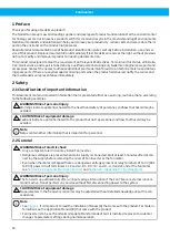
sure value for the PID1 controller is shown in the display as ‘PID1 Feedback’, and the unit adjusts the speed of
the fan in order to keep a constant pressure in accordance with the reference setpoint, ‘PID1 Setpoint’, which is
set in the ‘Control page’. See
: the ‘Control page’ displays ‘Keypad SP1’.
The factory setting of 900 Pa is a useful start value for an extraction arm, but the setpoint can be adjusted to
a value that gives the correct airflow from the extraction points. A second setpoint value for a higher or lower
pressure value can be set as ‘Keypad SP2’. This second setpoint, is used when Digital Input DI3 is activated.
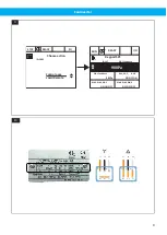
The range for the pressure sensor is 0–2000 Pa or 0–5000 Pa and output is 0,5–4,5 V. It is connected to AI2
(analogue input 2). The lower port (minus) is connected with a silicon hose to the measurement hose.
5.2 Pressure measurement
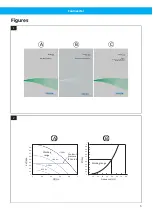
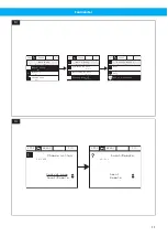
A pressure tap with filter is to be inserted in the duct at a location where the greatest pressure drop is expec-
ted to occur, normally at the most distant extraction point. In this way, the required pressure in the connection
point for an extraction arm, for example, can be controlled, compensating for a pressure drop in the filter and
duct system. See
(A).
If the duct system is equally branched, pressure taps can be used at the ends of the two branches with the
highest pressure drop, and connect them with equal lengths of hose before the pressure signal to the unit in or-
der to get an average pressure value. See
(B).
Note
Transport velocity needs to be dimensioned correctly and adjustment dampers may be needed in extrac-
tion points closer to the fan.
5.3 Pressure measurement using pressure loss compensation
Note
• This is not the recommended installation.
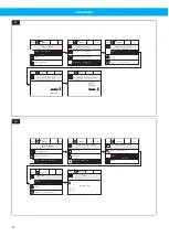
• ‘PID1 Feedback’ displayed in the Multimonitor page, see
, is not a fixed value set in the control
page ‘Keypad SP1’.
• It is not recommended that supervision be used with pressure loss compensation, see
If the system is complex with many branches, the pressure can be measured and controlled using ‘pressure drop
compensation’. A pressure tap is inserted in a common duct closer to the fan but before any filter.
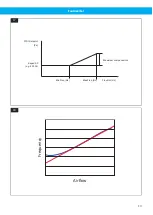
To compensate for the increasing pressure drop with increasing airflow, the PID1 set point is increased with a
compensation that increases with the frequency. Compensation is calculated using the formula below:
Setpoint compensa�on = Maximum compensa�on x
(FreqOut - MinFreq)
(MaxFreq - MinFreq)
To set up pressure loss compensation, see
Section 12.3 Pressure loss compensation settings
18

