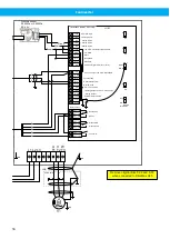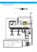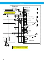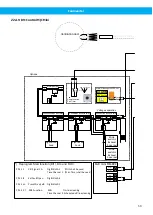
Fan Inverter
RO2/ 1 NC
24
RO2/ 2 CM
25
RO2/ 3 NO
26
+10V
1
+AI1
2
-AI1
3
+AI2
4
-AI2
5
+24V
6
GND
7
DI:1
8
DI:2
9
DI:3
10
CM
11
+24V
12
GND
13
DI:4
14
DI:5
15
DI:6
16
CM
17
+AO1
18
-AO/GND
19
RO1/ 1 NC
21
RO1/ 2 CM
22
RO1/ 3 NO
23
Run enable
Start
Not Ready
Ready
+10V ref Output
+ Analog Input 1
3~
=UE1
M1
+24 V DC Volt. Output Max 250mA
Aux. volt. common
Common Digital input (DI:1 DI:6)
GND
I/O GND
Aux. volt. 24 V DC Max 250mA
+ Analog Output: 0-10V = 0-max freq. Hz
- Analog Output
32
33
+24V In
30
External input +24 V DC
-RS485
A
+RS485
B
Relay output
PTC
RO3/ 1 CM
RO3/ 2 NO
Pressure OK
Pressure Low
Fan Timer
Green
Brown
White
Constant freq.
Disable/Reset Timer
Setpoint 2
Ov2h
2
3
1
Safety Switch
Remove Link 6-9 if Safety Switch
control signal is connected
1
2
3
4
5
6
Remove original links 8-32 and 9-33
when connected to FilterMax
- Analog Input 1
+ Analog Input 2
- Analog Input 2
13
14
2
1
2
Remove link 25-32 if start control from
external contact is used.
Connect external contact to terminal 32
for a serial connection with Fan Timer,
or to terminal 33 if Fan Timer shall not
be used.
RO1
25
RO2
26
TI1+
28
TI1-
29
PTC Input
Galvanic isolated
Optional STO and ATEX (PTC) board OPTBJ
Diagnostic
STO1+
1
STO1-
2
STO2+
3
STO2-
4
X23
On Off
X10
STO JMP
Thermistor short
circuit supervision
STO JMP
STO inputs (Emergency stop)
See Vacon Manual for OPTBJ
1
U
I
AI1
U
I
AI2
U
I
AO
OFF
ON
RS-485
termination
DIO’s
FLOAT
GND
Inverter Vacon 100 HVAC
Pressure sensor
0-2000Pa or 0-5000Pa
0,5-4,5V
54

